3 connection diagram c520, Electrical connections – INOR IPAQ R520X User Manual
Page 16
4
ELECTRICAL CONNECTIONS
C520/C520X / R520/R520X
09/2010 • 86B5200001
www.inor.com
16
4.3 Connection diagram C520
ATTENTION!
To enable HART communication, the output circuit must have an output load of at least 250
Ω
.
ATTENTION!
C520 is a Category 3 equipment and the transmitter may not be operated in areas with
potentially explosive atmospheres other than Zone 2 and Division 2!
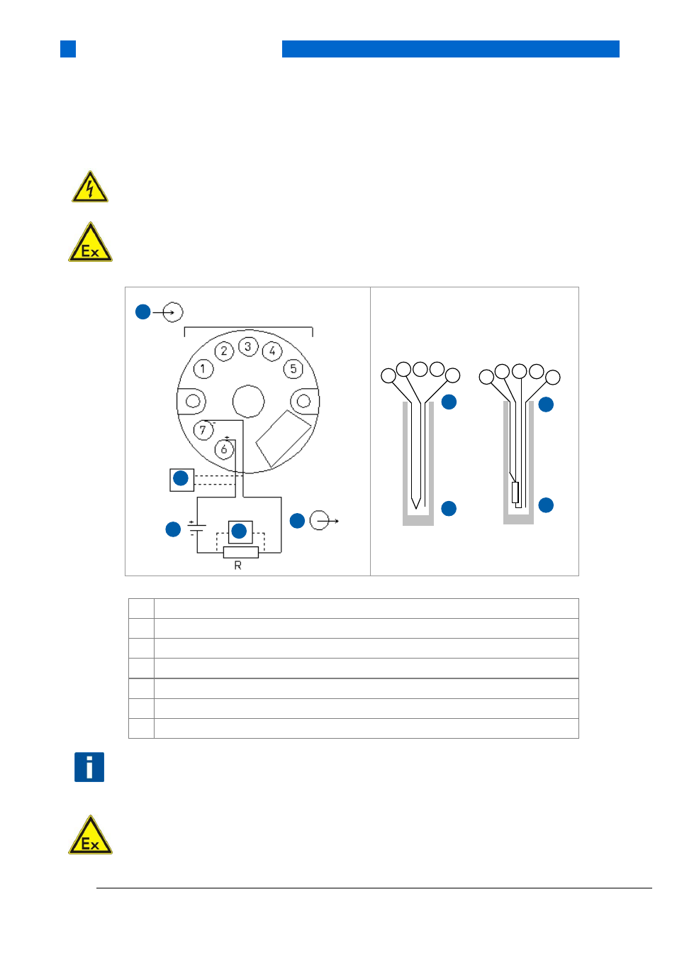
Figure 7: C520 connection
1
Voltage supply 10…36 VDC (terminals 6, 7)
2
Input
3
Output
4
Modem
5
SmartSense temperature sensor
6
Thermocouple
7
Pt100 3 wire connection
NOTE!
The HART modem is connected parallel to the output load or parallel to the output of the
transmitter (see Figure 7).
ATTENTION!
IPAQ C520 may be operated in areas with potentially explosive atmospheres (Zone 2 and Division
2) if the power supply has a protection ensuring that the power supply terminals of the
transmitter are limited to transients not exceeding 140% of the rated power supply.
1
2 3 4
5
1 2
3 4
5
6
5
5
7
2
1
3
4
4
USB