7 connection diagram, r520x, 8 cable length, Electrical connections – INOR IPAQ R520X User Manual
Page 23
4
ELECTRICAL CONNECTIONS
C520/C520X / R520/R520X
09/2010 • 86B5200001
www.inor.com
23
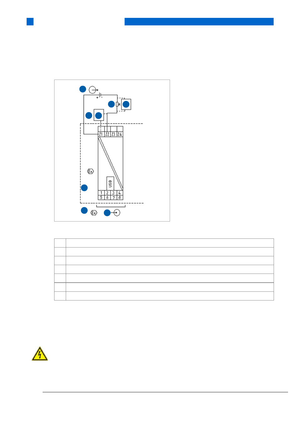
4.7 Connection diagram, R520X
Figure 14: R520X connection diagram
1
Voltage supply 10…30 VDC (intrinsically safe - terminals 21, 22)
2
Input (intrinsically safe)
3
R
Load
(intrinsically safe)
4
Modem / Ex (intrinsically safe)
5
Classified hazardous area (potentially explosive area e.g. Zone 0, 1 or 2)
6
Classified hazardous area (potentially explosive area e.g. Zone 1 or 2)
7
Safe area
4.8 Cable length
In order to ensure reliable HART communication with C520/R520, the maximum cable length of
the output circuit must be observed.
ATTENTION!
In the Ex version, please note that the maximum cable length is determined by a resistance, an
inductance and a capacitance of the cable. The total capacitance and inductance of the cable
must be within the limits for the transmitter described in the Ex certificate.
2
1
3
6
5
4
4
7