Electrical connections – INOR IPAQ R520X User Manual
Page 21
4
ELECTRICAL CONNECTIONS
C520/C520X / R520/R520X
09/2010 • 86B5200001
www.inor.com
21
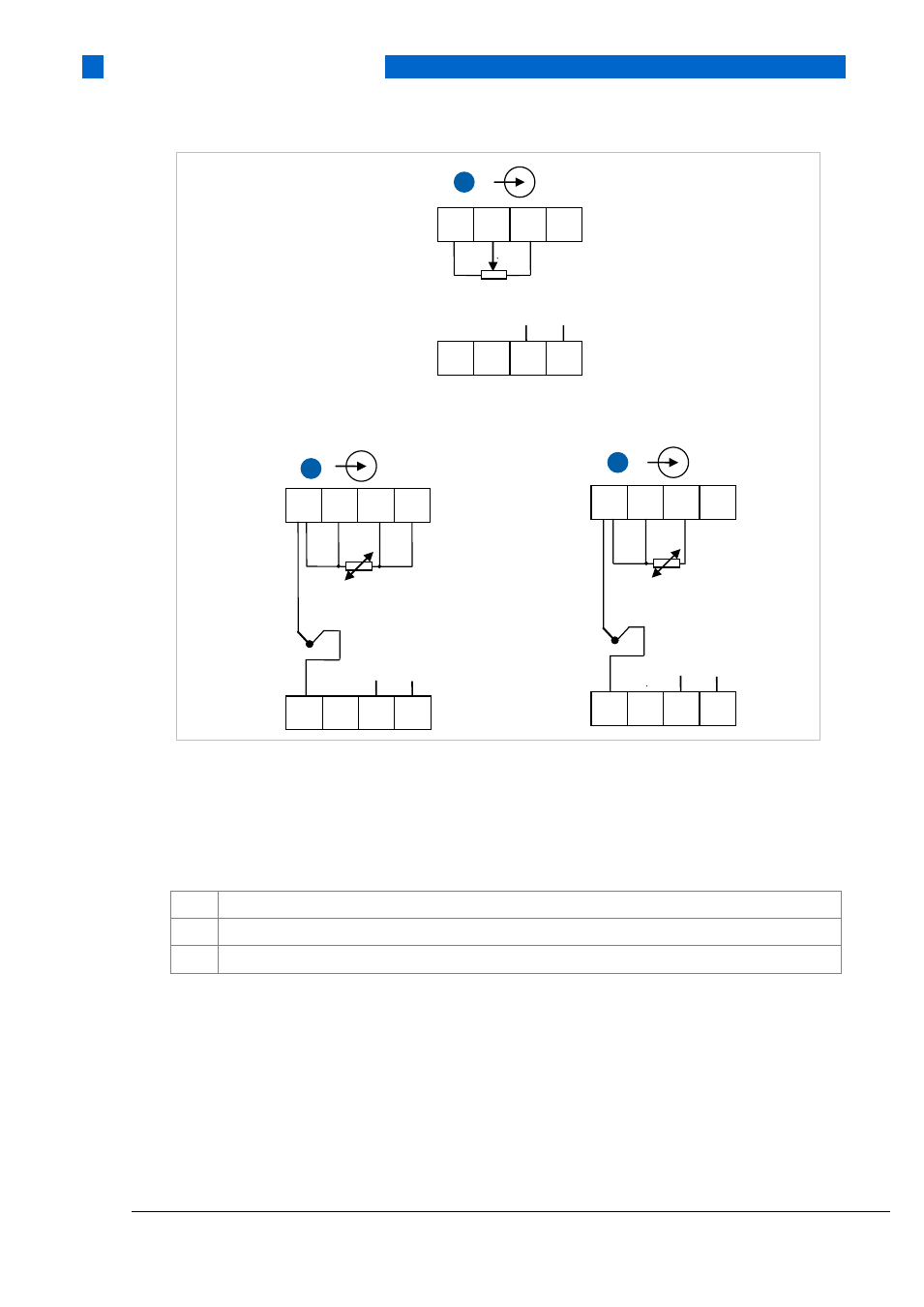
Figure 12: Installation diagram, potentiometer and combined thermocouple and RTD connections for R520/R520X
1) SmartSense wire
2) GND (input cable screen)
1
Potentiometer 3-wire connection
2
Thermocouple and redundant 4-wire RTD elements
3
Thermocouple with 3-wire RTD elements as external CJC
1
5
6
7
8
Ch 2
1
2
3
4
Ch 1
2)
1)
0%
100%
2
1
2
3
4
Ch 1
5
6
7
8
Ch 2
-
+
2)
1)
3
5
6
7
8
Ch 2
1
2
3
4
Ch 1
-
+
2)
1)
This manual is related to the following products: