En - 39 – HT instruments SOLAR300N User Manual
Page 41
SOLAR300 - SOLAR300N
EN - 39
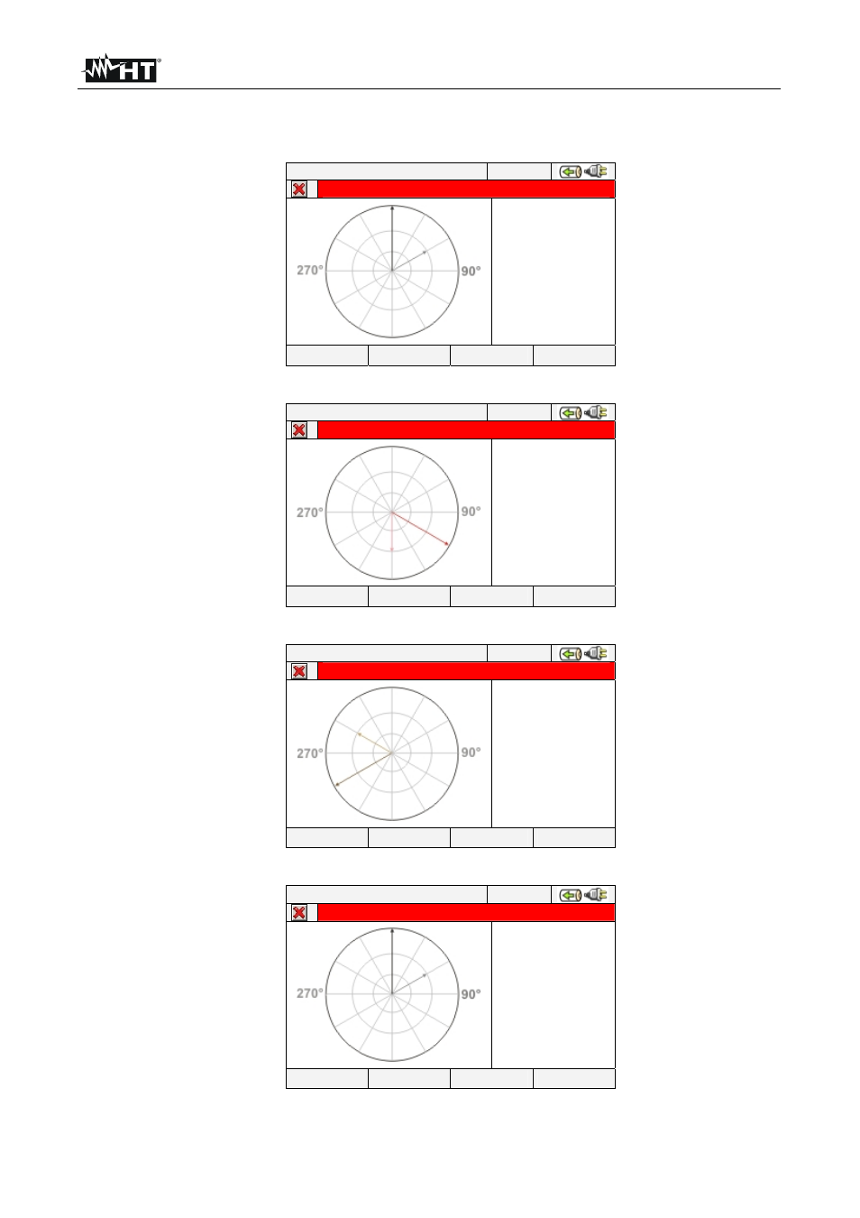
The vectorial diagram of voltage and current for each phase depending on the type of
system as shown in below screens:
12/09/2006 – 16:55:10
PHASE1 DIAGRAM – Page 4/6
V1^
I1
60.0°
PAGE
Fig. 85: Vectorial voltage-current diagram of L1 phase for 4-wire system
12/09/2006 – 16:55:10
PHASE2 DIAGRAM – Page 5/6
V2
^
I2
60.0°
PAGE
Fig. 86: Vectorial diagram voltage-current of L2 phase for 4-wire system
12/09/2006 – 16:55:10
PHASE3 DIAGRAM – Page 6/6
V3
^
I3
60.0°
PAGE
Fig. 87: Vectorial diagram voltage-current of L3 phase for 4-wire system
12/09/2006 – 16:55:10
PHASE1 DIAGRAM – Page 4/6
V12^
I1
60.0°
PAGE
Fig. 88: Vectorial diagram voltage-current of L1 phase for 3-wire and ARON systems