Caution – HT instruments SOLAR300N User Manual
Page 151
SOLAR300 - SOLAR300N
EN - 149
7.2.
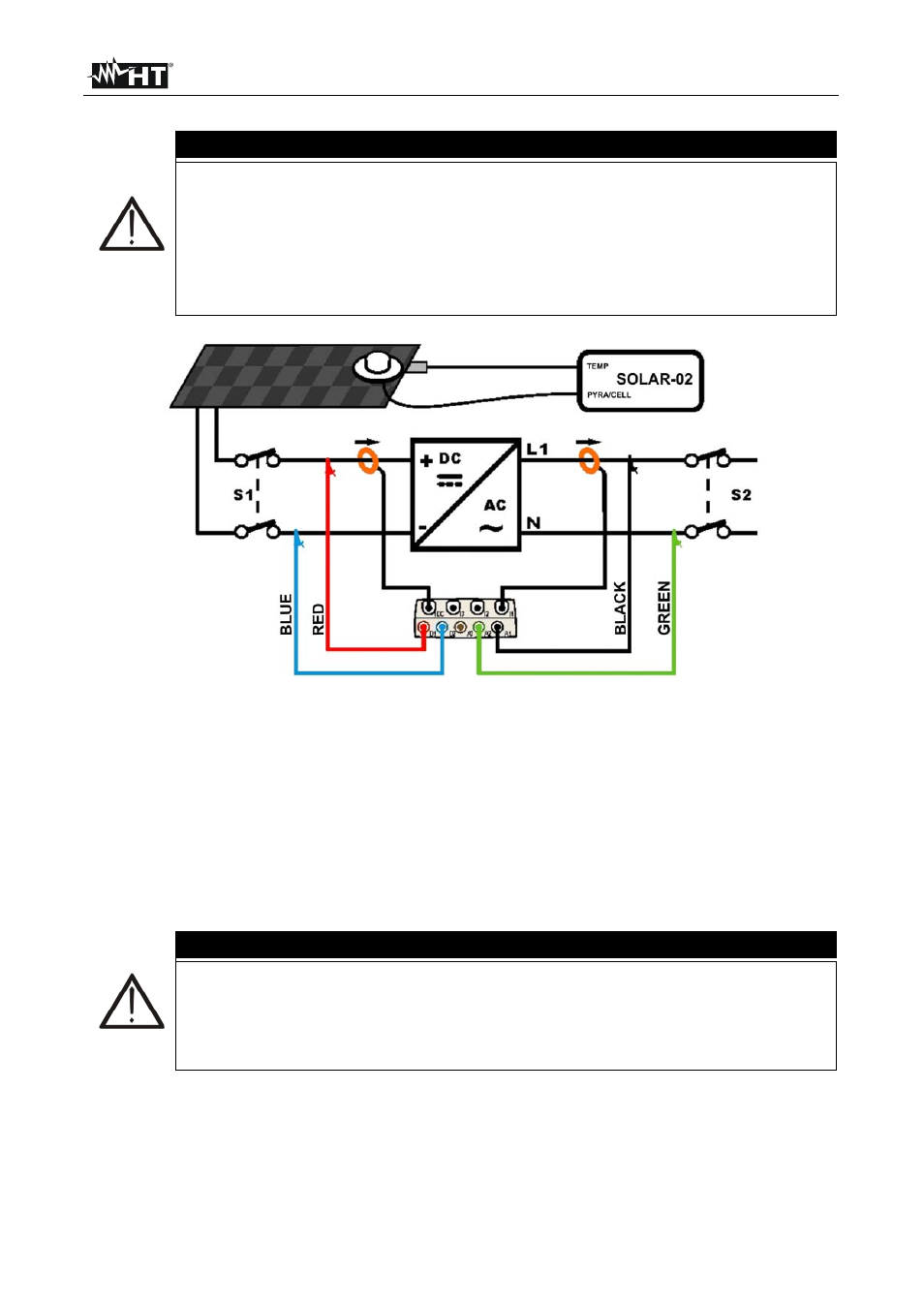
TEST OF PV-1 SYSTEM WITH REMOTE UNIT SOLAR-02
CAUTION
The maximum voltage between inputs D1, D2, A1, A2 and A3 is 1000V /
CAT IV 600V to earth. Do not measure voltages exceeding the limits
indicated in this manual. If these voltage limit values are exceeded, the
user may be exposed to electrical shocks and the instrument could get
damaged
Where possible, disconnect the connecting points of the instrument,
before connecting it, by means of disconnecting switches S1 and S2
Fig. 243: Connecting the instrument in a PV-1 system with SOLAR-02
1. Check and, if necessary, change the basic settings of the instrument relative to PV-1
configuration (see § 5.3.1, 5.3.2 and 5.3.3). Also check that the parameters of the
photovoltaic system considered correspond to the set values. For setting of
pyranometer or reference cell sensitivity please refer to the user manual of SOLAR-02
2. Use the remote unit SOLAR-02 in independent mode to perform a possible preliminary
measurement of irradiance
3. Connect inputs D1 and D2 to the positive and negative string output pole respectively.
Connect inputs A1 and A2 to the phase and neutral conductors, respecting the colors
as shown in Fig. 243
CAUTION
BEFORE CONNECT DC CLAMP ON CONDUCTOR
Turn on the clamp, select the correct range and press the ZERO key to the
DC clamp in order to eliminate possible residual magnetizations in the
clamp (values of current up to 0.02A are acceptable). Connect the output
of the clamp to the IDC input of the instrument
4. Connect the DC current clamp to the positive string output conductor by respecting
the direction of the arrow on the clamp itself as indicated in Fig. 243. Check the
status of internal batteries of the DC clamp after the connection to the
installation