Caution – Edwards Signaling 5541M-Y6 User Manual
Page 18
P/N 3100471 ISSUE 3
PAGE 18
When the
button is pressed, the panel will begin to poll all unit
addresses beginning at address 00 and ending at address 3F. As
devices are found, they are stored in the panel's device map. The
program setup will run two times for redundancy and reliability.
Once complete, the LCD screen with display:
AUTO LEARN COMPLETE
Press
button to advance to the next setup screen.
After running the Auto Learn mode, devices detected and stored in
the device map should be verified by the user in the Device Com-
mission program setup (See Section 3.4). Each configured device
can be viewed.
When devices are first stored in the device map, they are assigned
Dynamic Zone A. Dynamic zones for the individual devices can be
changed in the Device Zone Assignment Program Setup (See Sec-
tion 3.5).
NOTE:
In order for a device to receive a new Dynamic Zone
assignment, the panel must complete one successful poll
to the serial unit. Please allow approximately 1 minute for
poll completion prior to testing and verification of zones.
Only Master panels support Dynamic Zones.
3.10 - Zone to Input Assignment
Each serial device on the panel's RS-485 network can be assigned
a specific dynamic zone from A through D. Dynamic zone assigned
for each device configured in the device map is stored in non-
volatile memory. Each time a serial device is polled, its stored Dy-
namic Zone assignment command is sent out. When system audio
is initiated from the Master panel, those devices with matching
Dynamic Zones will broadcast the Master panel's system audio; all
other serial devices will be prohibited from the current audio broad-
cast.
NOTE:
Non-serial devices connected to the Master panel will
broadcast system audio for any and all zones.
1.
From the LCD screen, press the
button until LCD displays
"Zones: A B C D" as shown below. From this mode, both local
and external alarm inputs can be assigned to a combination of
zones (up to 4 zones maximum for each alarm input)
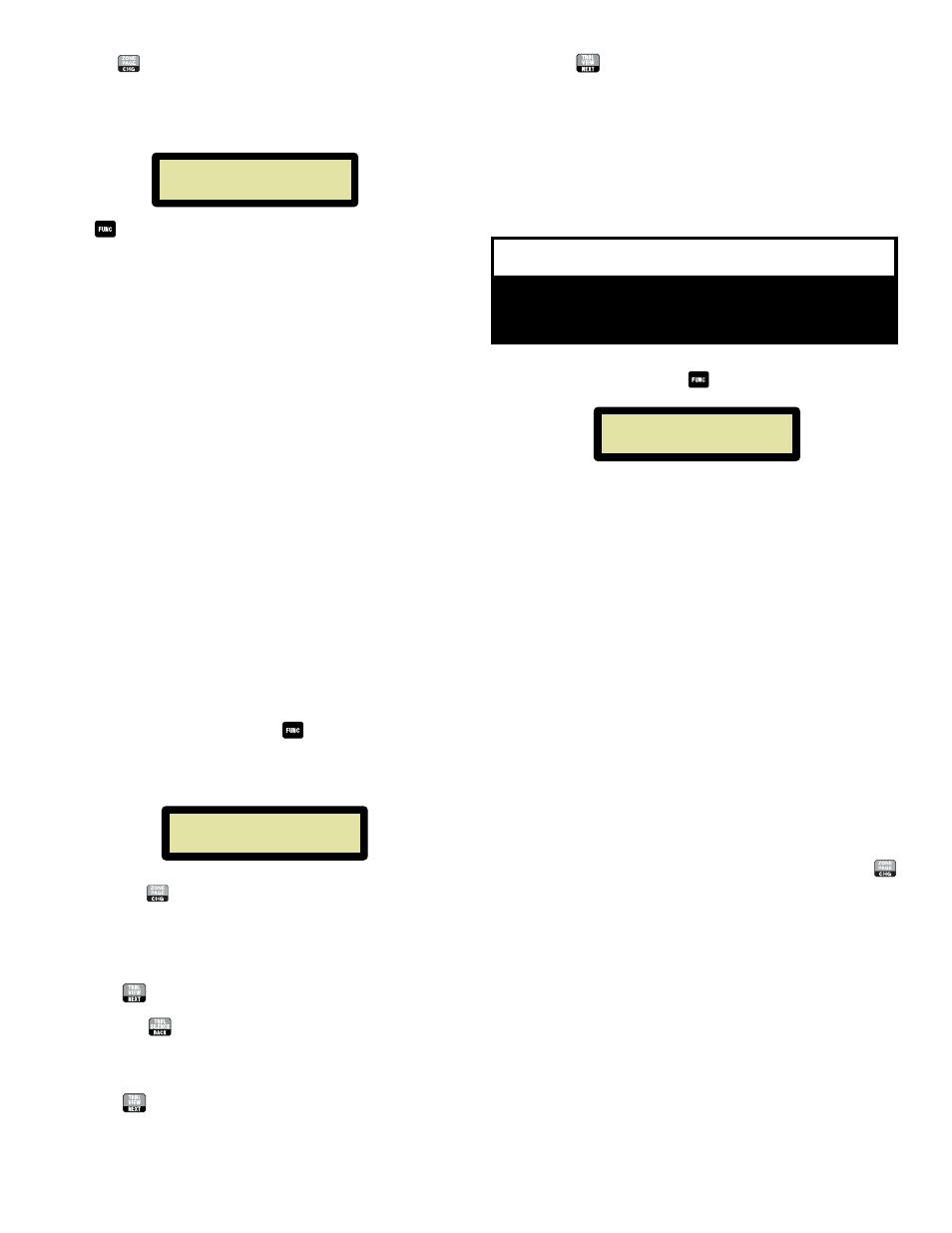
ZONES: A
B
C
D
Input 01 Y
Y
Y
Y
2.
To activate or deactive the current Zone for Alarm Input 1,
press the
button. More than one zone can be active for
each input.
NOTE:
"N" - the zone WILL NOT broadcast when the input is active
"Y" - the zone WILL broadcast when the input is active
3.
Press
to advance to the next zone. Repeat step 2.
NOTE:
Press
to return to the previously programmed relay.
4.
Repeat steps 2 and 3 to finish zone to input assignment on
Input 1.
5.
Press
to advance to the next alarm input, Input 2.
6.
Repeat steps 2 - 5 for each of the 4 local inputs as required.
7.
Pressing
after activation/deactivation of Zone D on Input
4 will advance to "Voice Message Setup" menu. See
Section 3.11.
3.11 - Voice Message Setup
The panel features voice messaging capability. This program setup
allows the user to easily record and store voice messages in four
separate message locations. Voice messages can then be selected
and assigned to Local Alarm Inputs in the "Local Inputs" Assign-
ment program setup screen.
Voice Message Setup
Location: 01 REC-OFF
From the LCD screen, press the
button until LCD displays:
CAUTION
The panel supervision must detect recorded audio in
each location or the panel will receive a trouble
indication.
This mode allows recording and storage of voice messages for later
playback. The panel supports up to four five-second voice mes-
sages. Message lengths greater than five seconds are possible by
extending the recording length.
Note:
Voice messages that become longer than five seconds will
physically require two or more message locations. For
example, a 20-second message would occupy all four
message locations limiting the user to only ONE message.
If a 20-second message is desired, record only in the first
message location (tone 17) and assign this location to any
four of the Local Alarm Inputs for playback. If other
locations are assigned for playback, the message may be
partial or incomplete. For a 15-second message, record in
the second message location (tone 18); for a 10-second
message, record in the third message location (tone 19).
Any of these messages can be assigned to any of the Local
Alarm Inputs.
To record a message:
1.
Press the microphone's press-to-talk (PTT) button and speak
clearly into the microphone. When finished recording, release
the PTT button.
2.
To advance to the next voice message location, press the
button.
3.
Repeat steps 1 and 2 until all desired messages have been
recorded.
NOTE:
To play back the message(s) that you have recorded,
cancel out of programming mode (by pressing) and activate
the local input with the voice message programmed on it.
If the voice message does not play, ensure that the input is
programmed to play the recorded message. See Section
3.2 and Table 1.