7 - connecting to output relay, External inputs – Edwards Signaling 5541M-Y6 User Manual
Page 12
P/N 3100471 ISSUE 3
PAGE 12
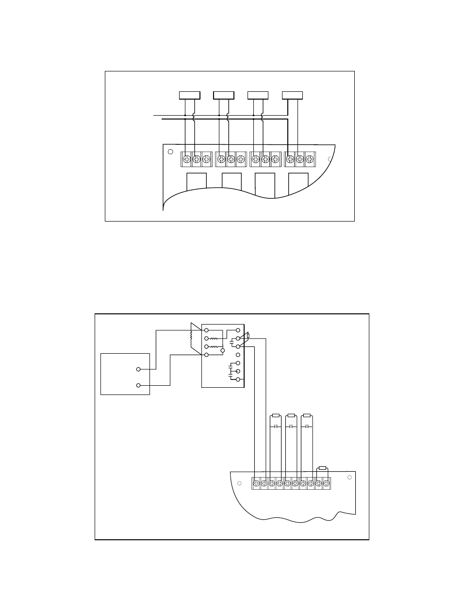
Figure 9. Connecting Output Relays (General Purpose)
2.7 - Connecting to Output Relay
Up to four loads can be connected to the external output relays.
Refer to Figures 3 and 9 for connections and to Appendix C, Panel
2.8 - Connecting External Initiating Input to Fire
Alarm Panel
The System Millennium Control Master can be connected to a fire
alarm panel for use in evacuation of the building. Connect the fire
alarm panel through a Cat. No. 6254B-003 relay to the console as
shown in Figure 10.
Figure 10. Connecting External Initiating Input to Fire Alarm Panel
Specifications, for maximum contact ratings. Output relays are fail-
safe; if the relay coil is faulty, power to the panel is lost or the relay
driver fails, the relay, although de-energized, will activate and the
load will be energized.
TB1
TB2
TB3
TB4
NO1
C1
NC1
NO2
C2
NC2
NO3
C3
NC3
NO4
C4
NC4
LOAD 1
LOAD 2
LOAD 3
LOAD 4
(N) 120V AC / -24V DC
(L) 120V AC / + 24V DC
NOTE: See Appendix C, Panel Specifications,
for Maximum Contact Ratings
EXTERNAL INPUTS
IN1
IN2
IN3
IN4
TAM
1
2
3
4
5
6
7
8
9
10
TB14
End-of-line resistor 4.7K
Cat. No. EOL-4.7
Pri 2
Pri 1
Pri 3
Pri 4
-
+
K1
K1
K1
680 OHM
3
4
1
Fire Alarm
Panel EOL
Resistor
2
22K
5
9
7
6
8
11
10
Polarity reverses
when in supervisory
mode
Polarity in
alarm condition
Fire Alarm Panel
Fire Alarm Relay Cat. No. 6254B-003
Listed under: URRQ.S6604
End-of-line resistor 4.7K
Cat. No. EOL-4.7
NOTE:
When the System Master is used with a fire alarm panel,
Standby Power MUST be installed and enabled.