Step 9: install column connections, Capillary columns, Figure 20. measuring column insertion – Agilent Technologies G6600-90006 User Manual
Page 61
Operation and Maintenance Manual
61
Step 9: Install Column Connections
The Burner operates under reduced pressure and there will be a slight vacuum
on the end of the column. If a higher outlet pressure for the column outlet is
desired, fused silica capillary restrictors may be attached to the end of the
analytical column (both capillary and packed) prior to making the Detector
connection.
Capillary Columns
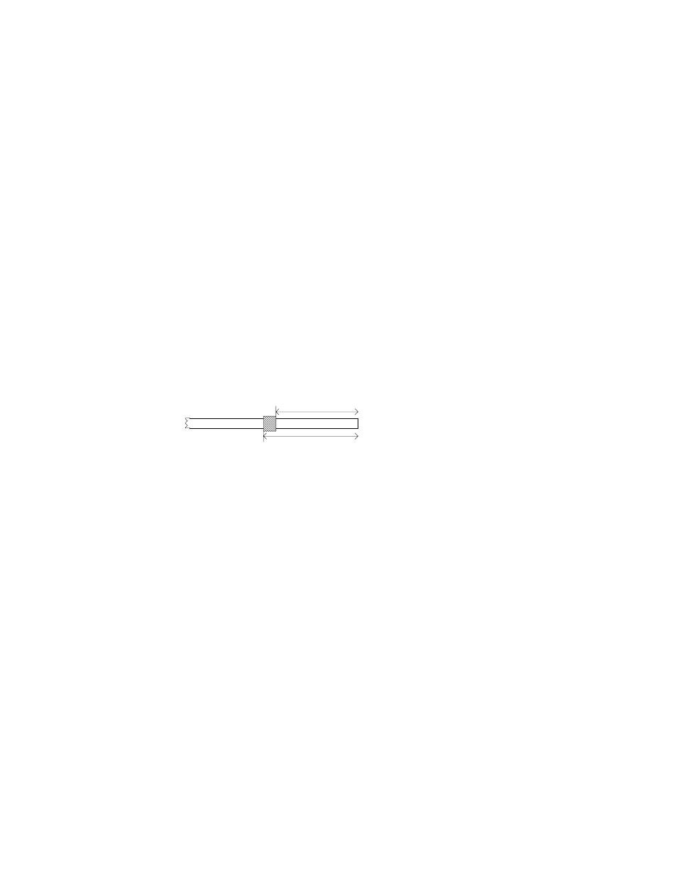
Place the column nut over the end of the capillary column. Place the
appropriate fused silica adapter ferrule onto column. Remove a few
centimeters from the end to remove any particles that may have entered the
column. Insert the GC column into the Burner by 108-109 mm from the upper
end of the nut (114-115 mm if measured from the flat bottom of the nut). Do
not force the column. The pathway is narrow and may take several tries to seat
it correctly. Tighten the column nut finger tight, or until sealed using a 7/16"
open-end wrench to back-up the hydrogen inlet fitting to prevent it from
slipping.
Packed Columns and Columns with an Outside Diameter > 0.8 mm
Connect a short piece (0.5 m or less) of deactivated fused silica tube, for
example 0.32 mm internal diameter, to the Detector end of the column. Follow
the procedure for capillary column connection as above.
Figure 20 Measuring Column Insertion
114-115 mm
108-109 mm