Step 4: connect the power cord, Figure 17. scd rear panel diagram – Agilent Technologies G6600-90006 User Manual
Page 56
56
Operation and Maintenance Manual
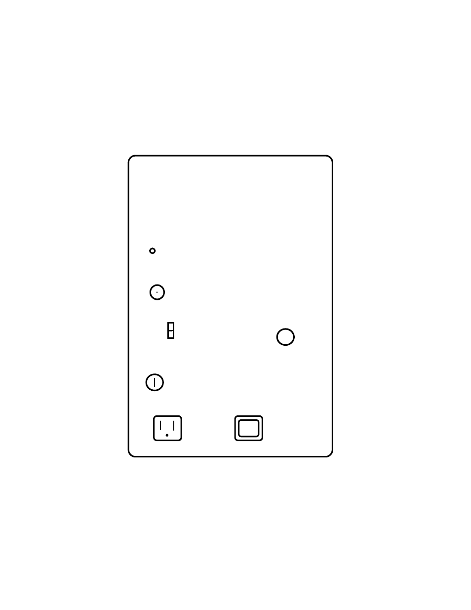
Step 4: Connect the Power Cord
Connect the pump power cord to the female socket on the back of the Detector
(see
). The pump has an
On/Off switch located on the electrical motor
and this switch should be turned On. Do not connect to the AC power supply at
this point in the installation procedure.
Figure 17 SCD (230 V Unit) Rear Panel Diagram
AIR INLET
RECORDER
OUTPUT
FUSE 250 VOLTS
10 AMPS
VACUUM
PUMP
EXHAUST
10V
1V
100mV
Voltage Label