Operation and Maintenance Manual
37
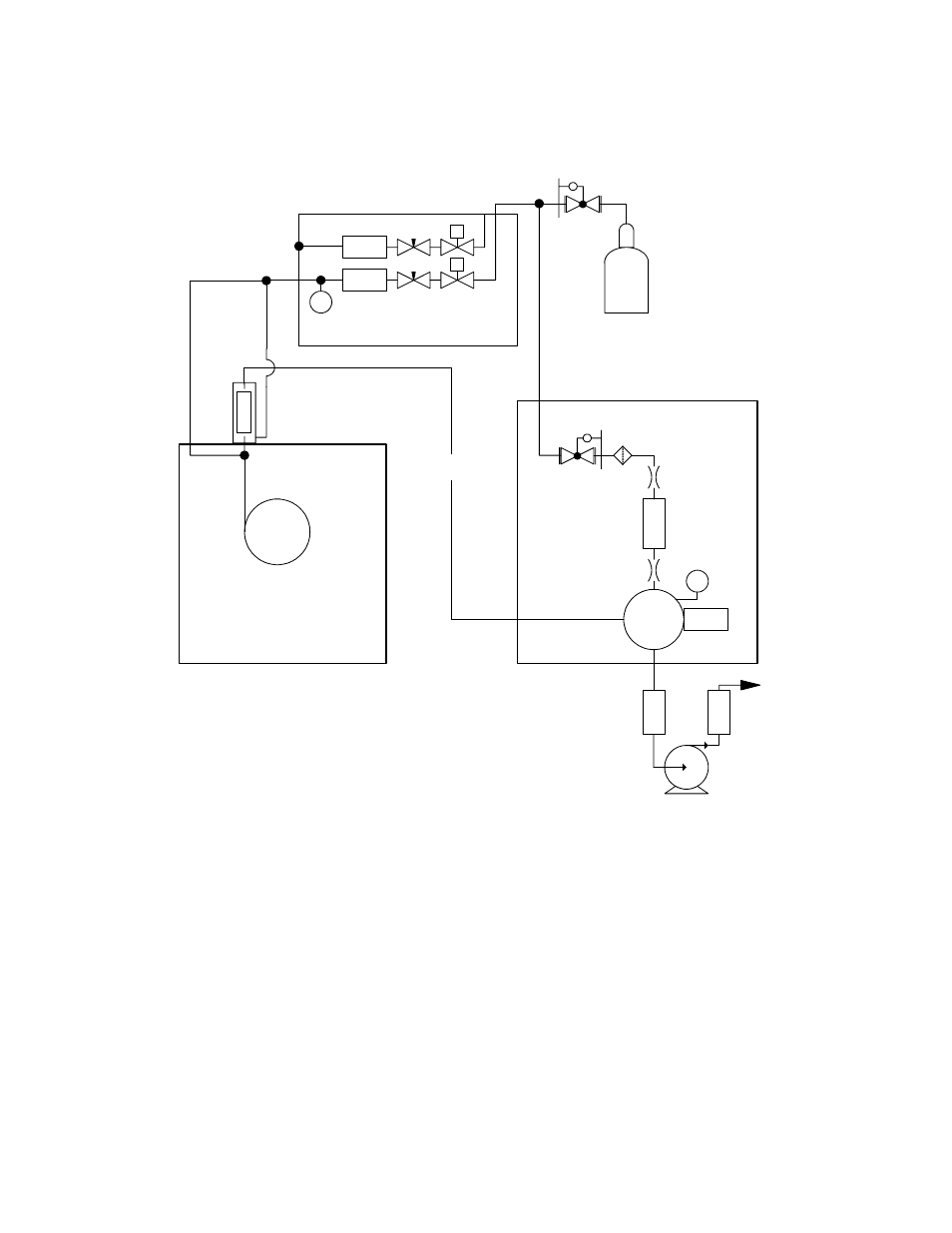
Figure 9
Schematic for 255 NCD, in Nitrosamine Mode
O
z
one
Vent
C
-Filt
e
r
O
2
*
Tr
a
p
PMT
Reaction
Cell
P
Transfer
Line
Column
Gas Chromatograph
255 NCD
Dual Plasma Controller
25 psig max
P
NC
S
F.C.
F.C.
Dual
Plasma
Burner
Mass
flow
Mass
flow
NC
S
C
a
ta
lyst
Vacuum Pump
*Or O
2
, He, N
2