36
Operation and Maintenance Manual
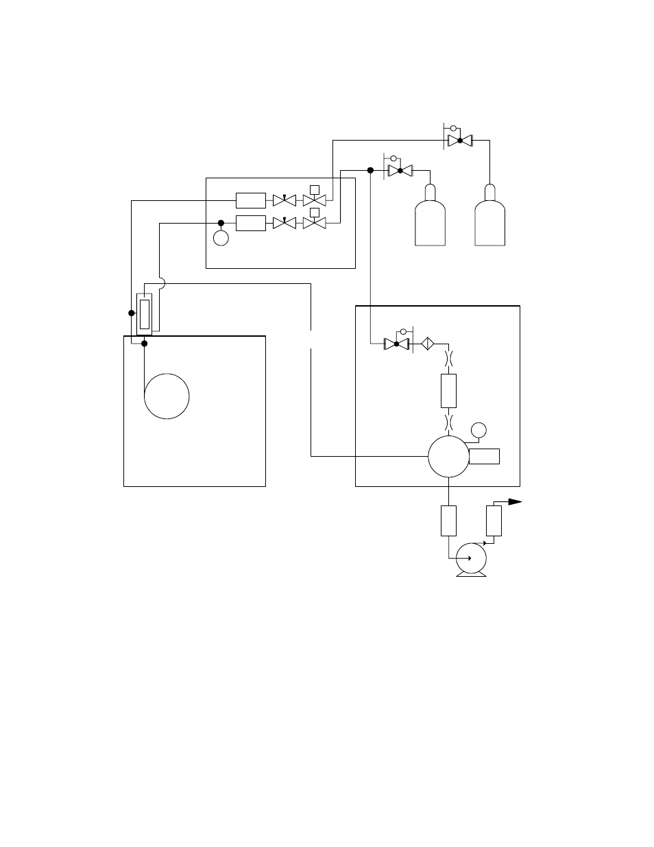
Figure 8
Schematic for 255 NCD, in Nitrogen Mode
Oz
one
Vent
C-F
il
ter
O
2
H
2
Tr
a
p
PMT
Reaction
Cell
P
Transfer
Line
Column
Gas Chromatograph
255 NCD
Dual Plasma Controller
25 psig max
25 psig max
P
NC
S
F.C.
F.C.
Dual
Plasma
Burner
Mass
flow
Mass
flow
NC
S
Cat
a
ly
st