Commissioning, 1 terminal & protection status display, 2 keypad status display – Sterling RT User Manual
Page 40
39
SV01H
Commissioning
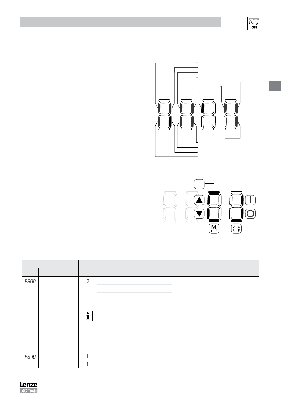
4.5.7.1 Terminal & Protection Status Display
Parameter P530 allows monitoring of the control terminal
points and common drive conditions:
An illuminated LED segment indicates:
• the protective circuit is active (LED 1)
• the Logic Assertion Switch is set to High (+)
• input terminal is asserted (LED 2)
• output terminal is energized (LED 4)
• the Charge Relay is not a terminal, this segment will
be illuminated when the Charge Relay is energized
(LED 4).
Charge Relay
Input (13C)
Input (13A)
Factory Reserved
Protective Diagnostic
Current Limit Diagnostic
Logic Assertion Switch
Input (1)
Input (13B)
Relay
Output (14)
Input (13D)*
* Input 13D available on 15-30HP (11-22kW) models only
LED #
1
2
3
4
4.5.7.2 Keypad Status Display
Parameter P531 allows monitoring of the keypad pushbuttons:
An illuminated LED segment indicates when the button is depressed.
LED 1 and LED 2 are used to indicate pushbutton presses on a remote
keypad that is attached to the drive. LED 3 and LED 4 indicate button
presses on the local drive keypad.
CTRL
4.5.8
Onboard Communications Parameters 15-30HP (11-22kW)
The P6xx Onboard Communication parameters are applicable to the 15HP (11kW) and greater models only.
Code
Possible Settings
IMPORTANT
No.
Name
Default Selection
p 0
Network Enable
0
0 Disabled
This parameter enables the onboard network
communications.
1 Remote Keypad
2 Modbus
7 Lecom
NOTE: Onboard Communications will be disabled if:
- P600 = 0, or
- P600 = 1 and P400 = 1, or
- P600 = 2 and P400 = 2, 3, 4, 5, 6 or 7
- P600 = 7 and P400 = 2, 3, 4, 5, 6 or 7
If the onboard communications are disabled, the user will not have access to any of the
other P6xx parameters.
Network Address
1 - 247
Modbus
1 - 99
Lecom