Commissioning, 3 advanced setup parameters – Sterling RT User Manual
Page 32
31
SV01H
Commissioning
4.5.3
Advanced Setup Parameters
Code
Possible Settings
IMPORTANT
No.
Name
Default Selection
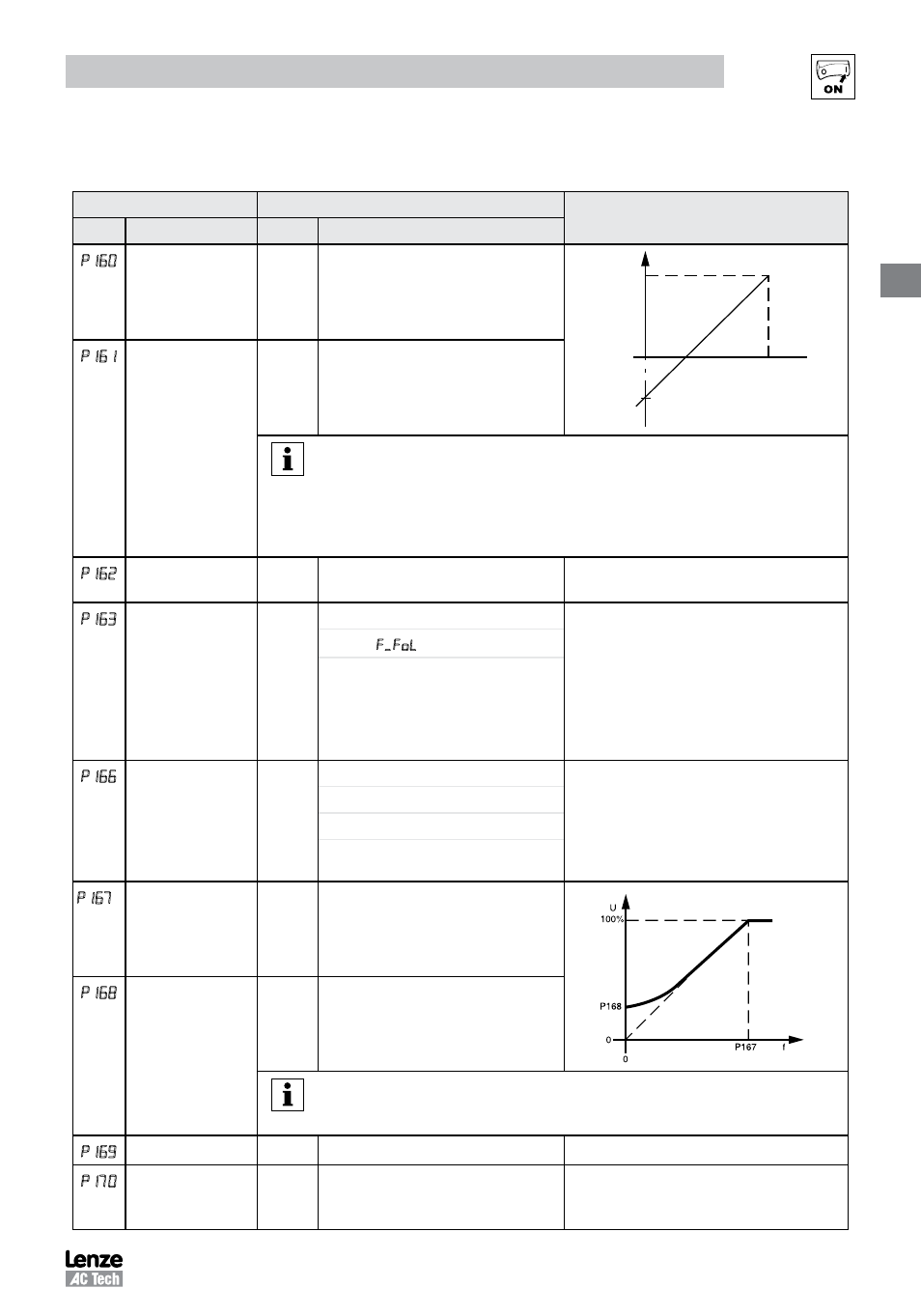
P 0
Speed at Minimum
Signal
0.0
-999.0
{Hz}
1000
f
P161
P160
ref
10V
(20mA)
0V
(4mA)
V0111
1
Speed at Maximum
Signal
60.0
-999.0
{Hz}
1000
NOTE
• P160 sets the output frequency at 0% analog input
• P161 sets the output frequency at 100% analog input
• P160 or P161 < 0.0 Hz: For scaling purposes only; does not indicate opposite
direction!
• P160 > P161: Drive will react inversely to analog input signal
Analog Input Filter
0.01
0.00
{s}
10.00
Adjusts the filter on the analog inputs (TB-5
and TB-25) to reduce the effect of signal noise
P 63
TB-25 Loss Action
0
0 No Action
• Selects the reaction to a loss of the 4-20
mA signal at TB-25.
• Signal is considered lost if it falls below 2
mA
• Digital outputs can also indicate a loss of
4-20 mA signal; see P140, P142
1 Fault
2 Go to Preset when TB-25 is:
Speed reference: P137
PID feedback source: P137
PID setpoint reference: P233
Torque reference: P333
P
Carrier Frequency
See
Notes
0 4 kHz
• As carrier frequency is increased, motor
noise is decreased
• Observe derating in section 2.3
• Automatic shift to 4 kHz at 120% load
• NEMA 4X (IP65) Models: Default = 0 (4kHz)
• NEMA 1 (IP31) Models: Default = 1 (6kHz)
1 6 kHz
2 8 kHz
3 10 kHz
1
(1)
Base Frequency
60.0
25.0
{Hz}
1500
V0112
Fixed Boost
0.0
{%}
30.0
NOTE
• P167 = rated motor frequency for standard applications
• P168 = default setting depends on drive rating
p
Accel Boost
0.0
0.0
{%}
20.0
Accel Boost is only active during acceleration
P 0
Slip Compensation
0.0
0.0
{%}
10.0
Increase P170 until the motor speed no
longer changes between no load and full load
conditions.
(1) Any changes to this parameter will not take effect until the drive is stopped