Commissioning, 7 diagnostic parameters – Sterling RT User Manual
Page 39
38
SV01H
Commissioning
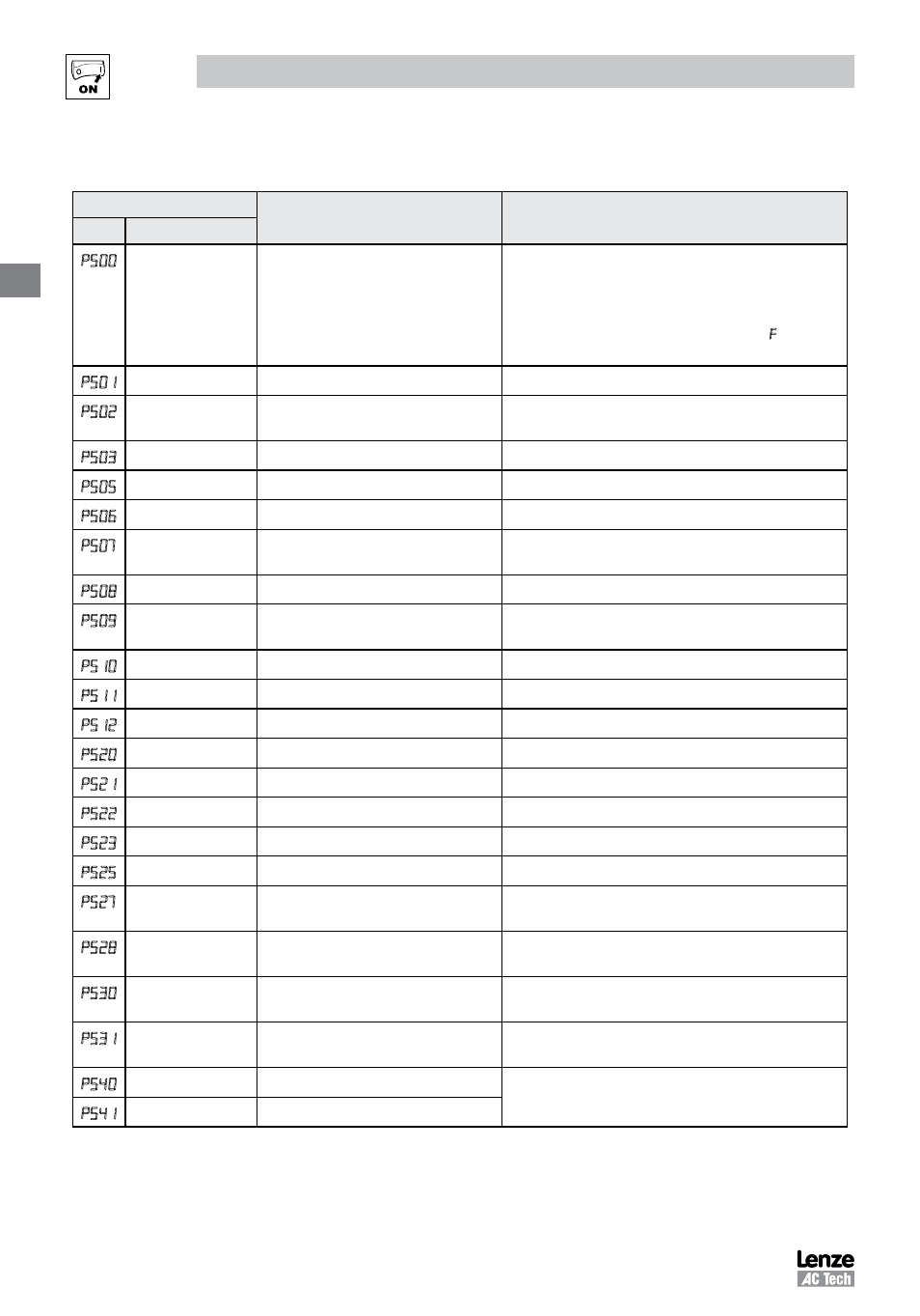
4.5.7
Diagnostic Parameters
Code
Display Range
(READ ONLY)
IMPORTANT
No.
Name
p 0
Fault History
• Displays the last 8 faults
• Format: n.xxx
where: n = 1..8;
1 is the newest fault
xxx = fault message (without the
.)
• Refer to section 5.3
P 1
Software Version
Format: x.yz
P 2
Drive ID
A flashing display indicates that the Drive ID stored in the
EPM does not match the drive model it is plugged into.
P
Internal Code
Alternating Display: xxx-; -yy
P
DC Bus Voltage
0
{VDC}
1500
P
Motor Voltage
0
{VAC}
1000
P 7
Load
0
{%}
255
Motor load as % of drive’s output current rating.
Refer to section 2.3.
P
Motor Current
0.0
{A}
1000
Actual motor current
P
Torque
0
{%}
500
Torque as % of motor rated torque
(vector mode only)
0
kW
0.00
{kW}
650.0
P 1
kWh
0.0
{kWh}
9999999 Alternating display: xxx-; yyyy when value exceeds 9999
P 2
Heatsink Temp
0
{°C}
150
Heatsink temperature
P 0
0-10 VDC Input
0.0
{VDC}
10.0
Actual value of signal at TB-5
P 1
4-20 mA Input
0.0
{mA}
20.0
Actual value of signal at TB-25
P 2
TB-5 Feedback
P204
P205
TB-5 signal value scaled to PID feedback units
P
TB-25 Feedback
P204
P205
TB-25 signal value scaled to PID feedback units
Analog Output
0
{VDC}
10.0
Refer to P150…P155
7
Actual Output
Frequency
0
{Hz}
500.0
P 8
Network Speed
Command
0
{Hz}
500.0
Command speed if (Auto: Network) is selected as the
speed source
P 0
Terminal and
Protection Status
Indicates terminal status using segments of the LED
display. (Refer to section 4.5.7.1)
1
Keypad Status
Indicates keypad button status using segments of the
LED display. (Refer to section 4.5.7.2)
P 0
Total Run Time
0
{h}
9999999 Alternating display: xxx-; yyyy when value exceeds 9999
P 1
Total Power On Time 0
{h}
9999999