Installation – Sterling RT User Manual
Page 19
18
SV01H
Installation
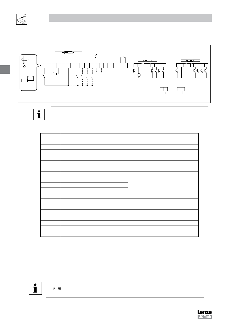
Control Terminal Strip for 15HP (11 kW) and Greater Drives:
6 25 4 11 13A13B 13C
TXA
5
1 2
14 30 2
AOUT
DIGOUT
2k … 10k
+10 V
+12 V
AIN
AIN
COM
COM
ALsw
17
16
TXB
13D
13D
13D
25
2
4 … 20 mA
5
2
0 … 10 V
1 2 4 13A 13B 13C
+12 VDC 0 %
+30 VDC + 0 %
ALsw
+15V
1 2 4 13A 13B 13C
ALsw
COM
4 5 lb in
(0 5 Nm)
0 25 in (6 mm)
AWG 26 16
(<1mm²)
NOTE
Control and communications terminals provide basic insulation when the drive is connected to a
power system rated up to 300V between phase to ground (PE) and the applied voltage on terminals
16 and 17 is less than 250 VAC between phase phase and ground (PE).
Terminal
Description
Important
1
Digital Input: Start/Stop
input resistance = 4.3k
Ω
2
Analog Common
5
Analog Input: 0...10 VDC
input resistance: >50 k
Ω
6
Internal DC supply for speed pot
+10 VDC, max. 10 mA
25
Analog Input: 4...20 mA
input resistance: 250
Ω
4
Digital Reference/Common
+15 VDC / 0 VDC, depending on assertion level
11
Internal DC supply for external devices
+12 VDC, max. 50 mA
13A
Digital Input: Configurable with P121
input resistance = 4.3k
Ω
13B
Digital Input: Configurable with P122
13C
Digital Input: Configurable with P123
13D*
Digital Input: Configurable with P124
14
Digital Output: Configurable with P142, P144
DC 24 V / 50 mA; NPN
30
Analog Output: Configurable with P150…P155
0…10 VDC, max. 20 mA
2*
Analog Common
TXA*
RS485 TxA
TXB*
RS485 TxB
16
Relay output: Configurable with P140, P144
AC 250 V / 3 A
DC 24 V / 2 A … 240 V / 0.22 A, non-inductive
17
* = Terminal is part of the terminal strip for the 15-30HP (11-22 kW) Models only.
Assertion level of digital inputs
The digital inputs can be configured for active-high or active-low by setting the Assertion Level Switch (ALsw) and P120.
If wiring to the drive inputs with dry contacts or with PNP solid state switches, set the switch and P120 to “High” (+). If
using NPN devices for inputs, set both to “Low” (-). Active-high (+) is the default setting.
HIGH = +12 … +30 V
LOW = 0 … +3 V
NOTE
An F L fault will occur if the Assertion Level switch (ALsw) position does not match the parameter
P120 setting and P100 or any of the digital inputs (P121...P124) is set to a value other than 0.