Installation, 3 mains connection to three-phase supply, 4 motor connection – Sterling RT User Manual
Page 16: 5 installation recommendations for emc compliance
15
SV01H
Installation
3.2.1.3
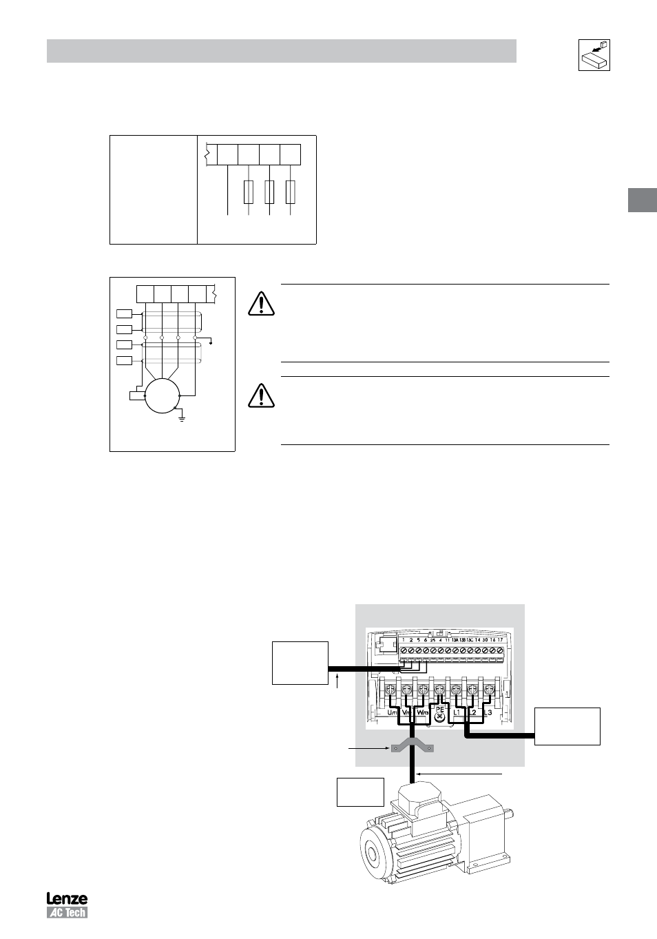
Mains Connection to Three-Phase Supply
ESV...N02Y...
ESV...N02T...
ESV...N04T...
ESV...N06T...
(3/PE AC)
PE L1 L2 L3
PE L1 L2 L3
3.2.1.4
Motor Connection
U
/
T1
V
/
T2
W
/
T3
PE
PES
PES
M
3~
PE
PES
PES
PES
PE
PES = Protective Earth Shielding
WARNING!
If the cable connection between the drive and the motor has an in-line contactor
or circuit breaker then the drive must be stopped prior to opening/closing the
contacts. Failure to do so may result in 0vercurrent trips and/or damage to the
inverter.
WARNING!
Leakage current may exceed 3.5 mA AC. The minimum size of the
protective earth (PE) conductor shall comply with local safety regulations
for high leakage current equipment.
3.2.1.5
Installation Recommendations for EMC Compliance
For compliance with EN 61800-3 or other EMC standards, motor cables, line cables and control or communications
cables must be shielded with each shield/screen clamped to the drive chassis. This clamp is typically located at the
conduit mounting plate.
The EMC requirements apply to the final installation in its entirety, not to the individual components used. Because
every installation is different, the recommended installation should follow these guidelines as a minimum. Additional
equipment (such as ferrite core absorbers on power conductors) or alternative practices may be required to meet
conformance in some installations.
Motor
cable
should
be
low
capacitance
(core/
core <75pF/m, core/shield
<150pF/m). Filtered drives
can meet the class A limits of
EN 55011 and EN 61800-3
Category 2 with this type of
motor cable up to 10 meters.
NOTE: Refer to Appendix A for
recommended cable lengths.
Any external line filter should
have its chassis connected to
the drive chassis by mounting
hardware or with the shortest
possible wire or braid.
From
Motor
Enclosure / Backplate
360° shield termination to
backplate using saddle clamp
Control and signal cabling
should be separated from
power cables by
a minimum of 300mm
Screened motor cable
core/core <75pF/M
core/shield <150pF/M
External
Control
Circuits
From
AC Supply