Commissioning – Sterling RT User Manual
Page 33
32
SV01H
Commissioning
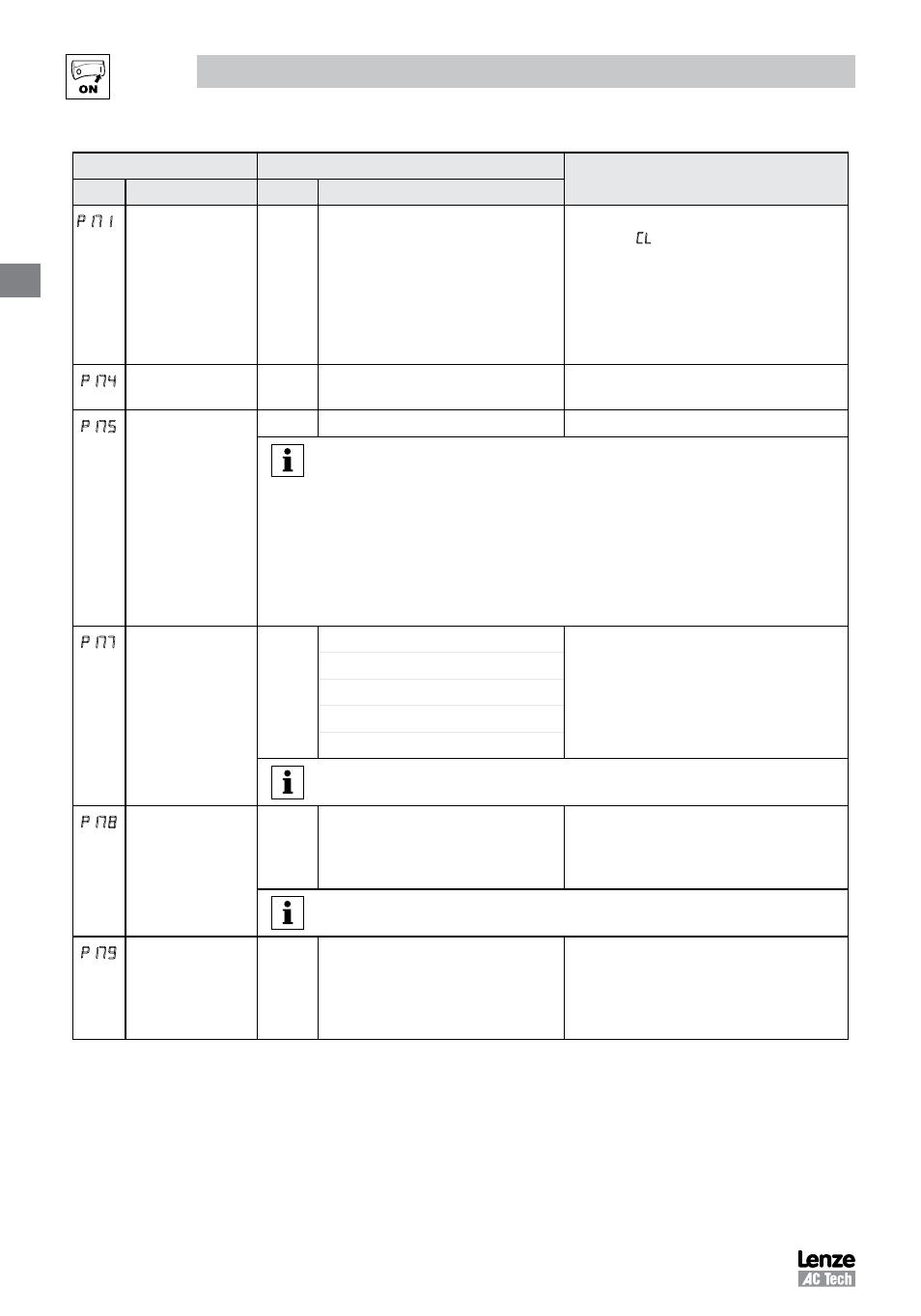
Code
Possible Settings
IMPORTANT
No.
Name
Default Selection
17
(1)
Current Limit
Max I
30
{%}
Max I
• When the limit is reached, the drive
displays (Current Limit), and either the
acceleration time increases or the output
frequency decreases.
• Digital outputs can also indicate when the
limit is reached; see P140, P142.
• Refer to section 2.3 for the maximum output
current
Max I (%)
DC Brake Voltage
0.0
0.0
{%}
30.0
Setting is a percent of the nominal DC bus
voltage.
p
DC Brake Time
0.0
0.0
{s}
999.9
NOTE
CONFIRM MOTOR SUITABILITY FOR USE WITH DC BRAKING
DC Brake voltage (P174) is applied for the time specified by P175 with the following
exceptions:
• If P111=1, 3 and P175=999.9 the brake voltage will be applied continuously until a
run or fault condition occurs.
• If P110=2, 4…6 and P175=999.9, brake voltage will be applied for 15s
• If P121…P124=18 and the corresponding TB-13 input is CLOSED, brake voltage will
be applied until the TB-13 input is OPENED or a fault condition occurs.
p 7
Speed Units
0
0 Hz
Select the UNITS LED that will be illuminated
when the drive is running in speed control
mode. For this parameter to be used, P178
must be set to a value other than 0. IF P178
is set to 0, the HZ LED will be illuminated
regardless of the value set in P177.
1 RPM
2 %
3 /UNITS
4 NONE
NOTE:
P177 is applicable to SMV 15HP (11kW) and greater models only.
Display Frequency
Multiplier
0.00
0.00
650.00
• Allows frequency display to be scaled
• P178 = 0.00: Scaling disabled
• P178 > 0.00: Display = Actual Frequency X
P178
EXAMPLE
If P178 = 29.17 and actual frequency = 60 Hz, then Drive displays 1750 (rpm)
p
Run Screen Display
0
0 {Parameter Number}
599
• 0 = Normal Run Screen, this display
depends on mode of operation.
Refer to section 4.2.
• Other selections choose a diagnostic
parameter to display (P501…P599).
(1) Any changes to this parameter will not take effect until the drive is stopped