2 calibration procedure, Calibration procedure -4, Ch10 – Yokogawa PC-Based MX100 User Manual
Page 53
4-4
IM MW180-01E
4.2 Calibration Procedure
Notes on Calibration
• Do not perform other operations during calibration. Take extra care because if you
perform another operation while calibration is in progress, the module may suffer a
break down.
• When the screw terminal block (model 772080) is connected to the 10-CH Medium-
Speed Universal Input Module, the terminal arrangement differs from that of clamp
terminals.
With the calibration software, modules with screw terminal blocks connected are
recognized as clamp terminals, meaning that the wiring diagrams show the wiring for
the clamp terminals.
Therefore when wiring and performing calibration, you must follow the markings
showing the terminal functions and the terminal codes indicating the types of signals
input to each terminal located on the back of the terminal cover of the 10-CH screw
terminal block.
Screw terminal block (model: 772080) terminal wiring markings.
CH1
1
2
CH2
3
4
CH3
5
6
CH4
7
8
CH5
11 RTD
11 RTD
9
10
CH6
1
2
CH7
3
4
CH8
5
6
CH9
7
8
CH10
9
10
Note: The b terminal is common to all channels.
The b terminals are connected internally.
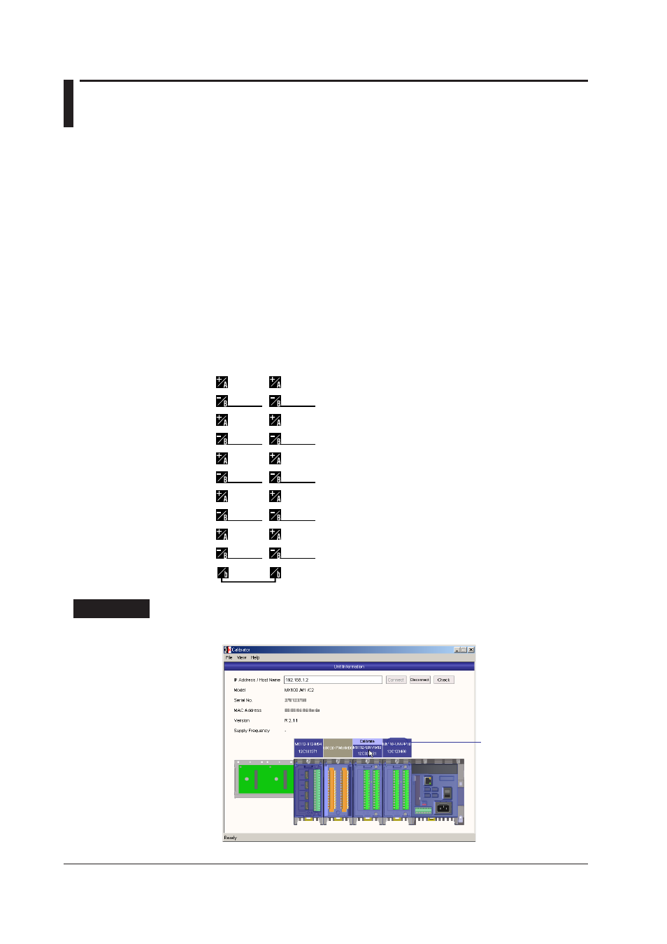
Procedure
1.
Click the illustration of the input/output module that you wish to calibrate.
Moving the cursor over
an module that can be
calibrated shows the
word “Calibrate”