Warning – Yokogawa Data Acquisition with PID Control CX2000 User Manual
Page 29
4-2
SM 04L31A01-01E
Replacement of Each Terminal Block (Module)
WARNING
• To prevent electric shock, cut the power to the main unit and disconnect any
wiring that may be connected to it before replacing the terminal block.
• To prevent electric shock when disconnecting wires, ensure the main power
supply is turned OFF.
Follow the procedures below to replace the blocks.
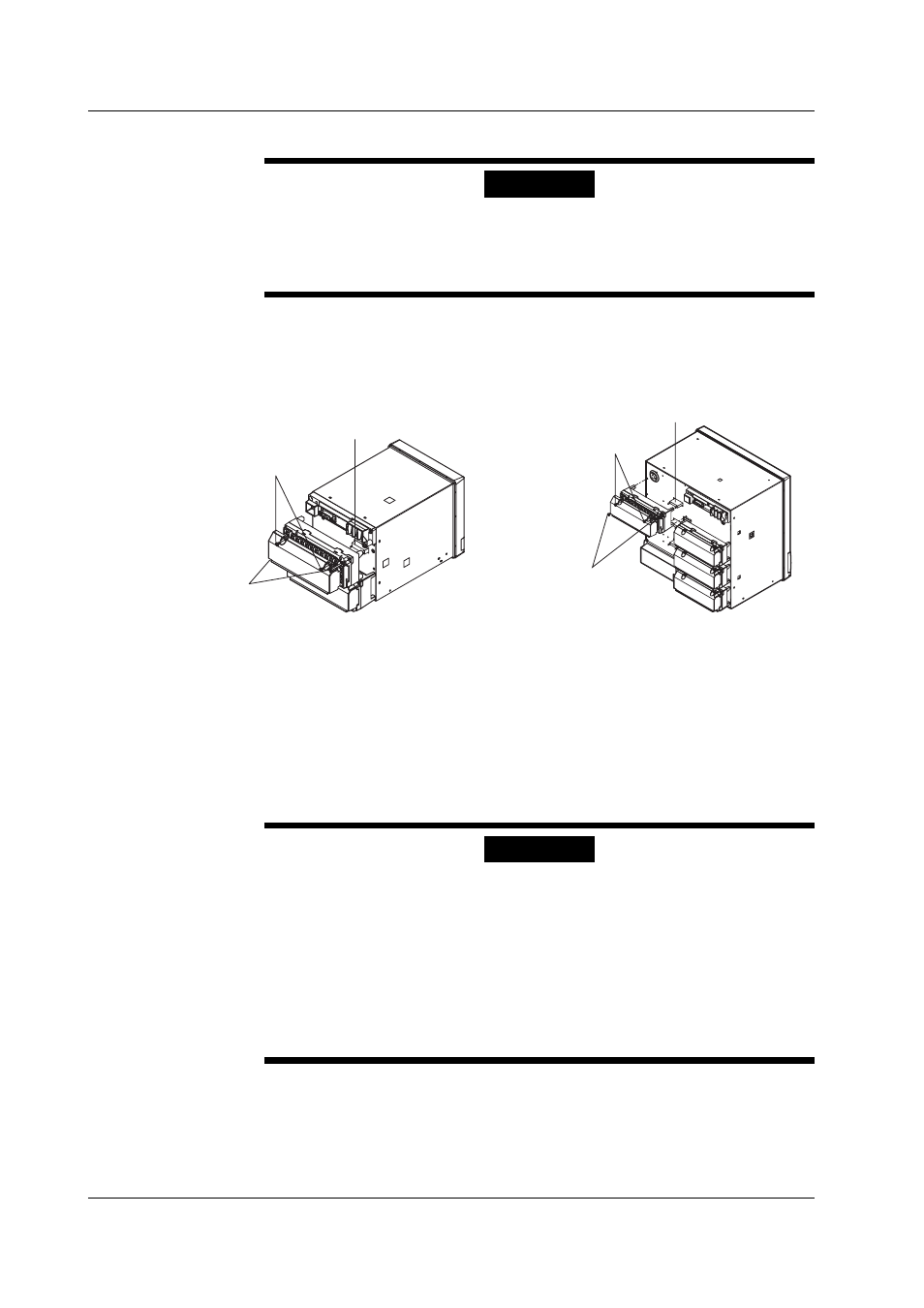
1 .
Loosen (but do not completely remove) the 2 terminal cover screws,
remove the cover, then remove the wiring from the terminal block.
Ignore this step if the terminal block is not wired.
Terminal cover screws
Terminal block attachment
screws
Connector
Terminal cover screws
Terminal block
attachment screws
Connector
2 .
Loosen the 2 terminal block attachment screws.
3 .
Pull the terminal block straight out and away from the unit. Be careful not
to bend the connector pins while removing the terminal block.
4 .
Check the angle of the terminal block, install it on the main unit, and then
fasten by tightening the terminal block attachment screws.
5 .
Install the terminal cover, and fasten with the terminal cover screws.
When Replacing Only the Control Relay
WARNING
• To prevent electric shock, unplug the main power cord before replacing
the control relay.
• To prevent electric shock when disconnecting wires, ensure the main
power supply is turned OFF.
• To prevent electric shock, use a withstanding voltage tester to check the withstanding
voltage between the relay and the protective grounding after replacing the relay.
Withstand voltage: 1500 VAC, 1 minute
• You must perform an insulation resistance test and wishstand voltage test
after replacing the control relay.
Follow the procedures below to replace the blocks.
1 .
Loosen (but do not completely remove) the 2 terminal cover screws,
remove the cover, then remove the wiring from the terminal block.
Ignore this step if the terminal block is not wired.
4.1 Replacement of the Control Output Terminal Block (Module)