Test of storage drive – Yokogawa Data Acquisition with PID Control CX2000 User Manual
Page 18
2-9
SM 04L31A01-01E
Testing
2
Test of Storage Drive
1.
Insert a formatted disk into the drive of the UUT.
2.
In the set mode*1, choose Save/Load, Clear data, and then Save settings. Save
the current panel conditions under a desired filename.
3.
In the set mode, choose Save/Load, Clear data, and then File list. Verify that the
file saved in step 2 exists in the list.
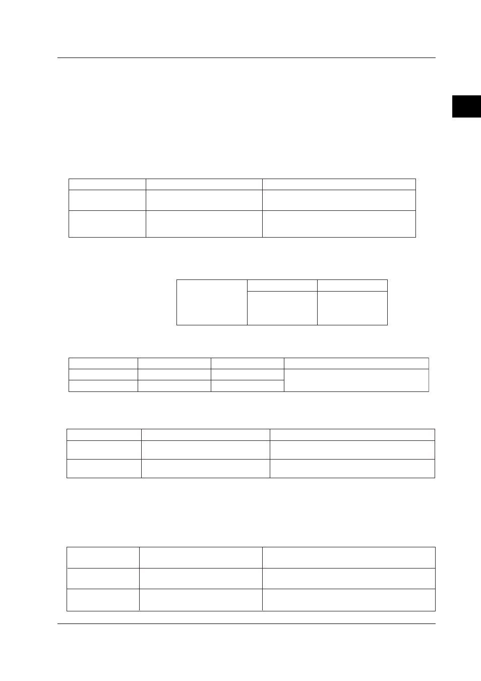
Test of Alarm Relay Contact Outputs (applicable to option codes /A6, /A6R, /A4F and /
A4FR)
Insulation Resistance and Withstanding Voltage Tests
Item
Measured Point
Specification
Insulation resistance
No less than 20 M
Ω at 500 V DC
Withstanding voltage
As above
Between relay output terminals and
grounding terminal
Free from damage after applying 1500 V AC,
50/60 Hz for 1 minute (with breaking leakage
current set to 2 mA)
Alarm Actions
1.
Prepare the same input terminals and settings as step 1 in “Digital Output”
(page 2-8), and also adjust the alarm relay output as follows:
Alarm
(Level 1)
Relay Output
On/off
No.
Ixx
where xx: alarm
output number to test
2.
Verify that an alarm contact works as follows upon turning on/off the
corresponding relay output.
Terminals
Normal
Remarks
NO–C
Break
Where the output relay action is set to
normally de-energized (factory set)
NC–C
Make
During Alarm
Make
Break
Test of Remote Control (applicable to option codes /A6R and /A4FR)
Insulation Resistance and Withstanding Voltage Tests
Item
Measured Point
Specification
Insulation resistance
Between remote control terminals and
grounding terminal
No less than 20 M
Ω at 500 V DC
Withstanding voltage
As above
Free from damage after applying 500 V DC for 2
minute (with breaking leakage current set to 2 mA)
Remote Control Actions
Assign individual functions to 8 remote control inputs, then short-circuit each of those
inputs in turn and verify that the CX1000/CX2000 is controlled as specified.
Test of 24 VDC Transmitter Power Output (applicable to option code /TPS4)
Test of Insuration Resistance and Withstanding Voltage
Withstanding voltage
Insulation resistance
Between 24 VDC output terminals and
grounding terminal
As above
Between 24VDC output terminals
No less than 20 M
Ω at 500 VDC
Free from damage after applying 500 VAC, 50/60 Hz for
1 minute (with breaking leakage current set to 10 mA)
Free from damage after applying 500 VAC, 50/60 Hz for
1 minute (with breaking leakage current set to 10 mA)
2.2 Test Procedures