Yokogawa AXFA14G/C User Manual
Page 51
IM 01E20C02-01E
6-22
6. PARAMETER DESCRIPTION
[F22: DO Active Mode] Setting of the active mode
for DO terminal
Operations are performed in accordance with the
following table when the active mode has been set to
“Closed (On) Act” using this parameter. Operating
patterns are reversed when the active mode has been
set to “Open (Off) Act.”
Selected function
Condition of DO terminal
Closed (On)
Open (Off)
Pulse Output
(see Example 1)
T0624.EPS
Open (Off) when
pulses are output.
Closed (On) when
pulses are output.
Alarm Output
(see Example 2)
Good (normal)
Good (normal)
Alarm status
Warning status
Warning Output
Total Switch(O)
(see Example 3)
Below setting value
Equal or above
setting value
Normal
Normal
H/L alarm status
HH/LL alarm status
Forward direction
Reverse direction
H/L Alarm(O)
HH/LL Alarm(O)
Fwd/Rev Rngs(O)
Note: For “Auto 2 Rngs(O),” “Auto 3 Rngs(O)”, “Auto 4 Rngs(O)”, and “Ext
2 Answer(O)”, see the Multiple ranges setting section.
[F23: DIO Active Mode] Setting of the active mode
for DIO terminal
Operations are performed in accordance with the
following table when the active mode has been set to
“Closed/Short Act” using this parameter. Operating
patterns are reversed when the active mode has been
set to “Open/Open Act.”
Selected function
Condition of DIO (O) terminal
Closed (On)
Open (Off)
T0625.EPS
Alarm Output
(see Example 2)
Good (normal)
Good (normal)
Alarm status
Warning status
Warning Output
Total Switch(O)
(see Example 3)
Below setting value
Equal or above
setting value
Normal
Normal
H/L alarm status
HH/LL alarm status
Forward direction
Reverse direction
H/L Alarm(O)
HH/LL Alarm(O)
Fwd/Rev Rngs(O)
Note: For “Auto 2 Rngs(O),” “Auto 3 Rngs(O)”, “Auto 4 Rngs(O)”, and “Ext
2 Answer(O)”, see the Multiple ranges setting section.
Selected function
Condition of DIO (I) terminal
Short
Open
0% Signal Lock (I)
(see Example 4)
T0626.EPS
Signal locked status
Ext Auto Zero (I)
Start of automatic zero adjustment
Forward totalization preset
Ext Ttl Set (I)
Ext R Ttl Set (I)
Reverse totalization preset
Normal
Normal
Normal
Normal
Note: For “Ext 2 Ranges(I),” see the Multiple ranges setting section.
*: “DIO (O)” indicates DIO function is used for output. “DIO (I)”
indicates DIO function is used for input.
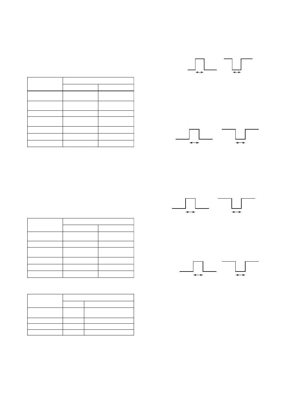
Example 1: When the “Pulse Output” function is
selected for the DO terminal and the E12:
Pulse Width is “1 ms”, the following
signals are output from the terminal.
F0604-1.EPS
1 ms
1 ms
Closed (On) Active
Open (Off) Active
Closed (On)
Open (Off)
Example 2: When the “Alarm Output” function is
selected for the DO or DIO (O) terminal,
the following signals are output from the
terminal.
Alarm occurs
Closed (On) Active
Alarm occurs
Open (Off) Active
F0604-2.EPS
Closed (On)
Open (Off)
Example 3: When the “Total Switch (O)” function is
selected for the DO or DIO (O) terminal,
the following signals are output from the
terminal.
Equal or above setting value
Closed (On) Active
Equal or above setting value
Open (Off) Active
F0604-3.EPS
Closed (On)
Open (Off)
Example 4: When the “0% Signal Lock (I)” function is
selected for the DIO (I) terminal, the
following signals are input to the terminal.
Signal lock status
Short Active
Signal lock status
Open Active
F0604-4.EPS
Short
Open