7 connecting to external instruments, Connecting to external instruments -7, 7 connecting to external instru- ments – Yokogawa AXFA14G/C User Manual
Page 19: Pulse output
IM 01E20C02-01E
4-7
4. WIRING
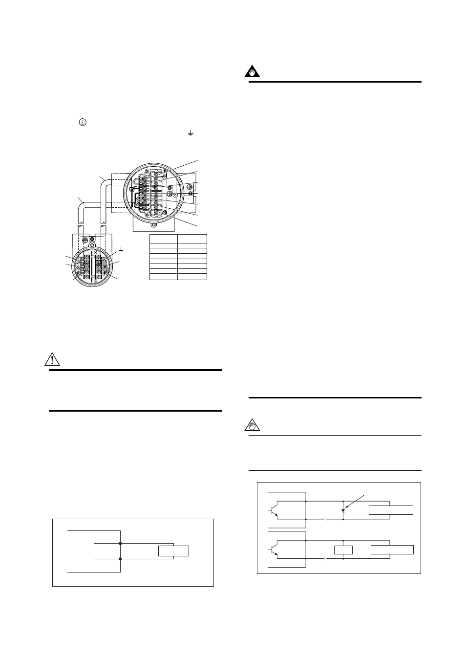
(2) Connection with the Remote Flowtube
(Explosion proof Type, Size 2.5 to 400 mm
(0.1 to 16 in.))
In case of explosion proof type for ATEX, FM, CSA,
IECEx and TIIS certification, connect wiring as shown
in the figure below.
In case of the explosion proof type, the protective
grounding
of remote flowtube must be connected to
a suitable IS grounding system. In that case,
(functional grounding terminal) need not be connected.
AXFC dedicated
signal cable
EX2
EX1
A
B
C
Excitation cable
EX1
EX2
C
SA
A
B
SB
F0414.EPS
Converter
Remote
flowtube
SA
A
B
SB
C
EX1
EX2
Taping*
A
B
Taping*
C
EX1
EX2
* Individually tape and insulate the
shields corresponding to SA and
SB on the remote flowtube side.
AXFA14 Converter
Remote flowtube
Figure 4.4.6
Wiring Diagram
4.4.7
Connecting to External Instru-
ments
WARNING
Before wiring with external instruments, be sure
to turn off the power supply for AXFA14
converter and any external instruments.
Connect the AXFA14 terminal to external instruments,
giving attention to the following points.
For F
OUNDATION
Fieldbus protocol, please refer to IM
01E20F02-01E.
For PROFIBUS PA protocol, please refer to IM
01E20F12-01E.
᭹ 4 to 20 mA DC Current Output
Resistive load max. 750
Ω.
(When using BRAIN/ HART communication,
more than 250
Ω, less than 600 Ω).
Receiver
Instrument
AXFA14
l+
l-
F0415.EPS
Figure 4.4.7
4 to 20 mA DC Output Connection
᭹ Pulse Output
IMPORTANT
• As this is a transistor contact (insulated type),
give attention to proper voltage and polarity
when wiring.
• Do not apply a voltage larger than 30V DC or a
current larger than 0.2A in order to prevent
damage to the instrument.
• When input filter constant of the electronic
counter is large in relation to the pulse width,
the signal will decrease and the count will not
be accurate.
• If the input impedance of the electronic counter
is large, an induction noise from the power
supply may result in inaccurate counts. Use a
shield cable or sufficiently reduce the input
impedance of the electronic counter within the
electromagnetic flowmeter pulse output specifi-
cation range.
• The active pulse output (Optional code EM)
cannot be used in conjunction with the standard
pulse output.
• When the active pulse output (Optional code
EM) is selected, do not be short-circuit between
the DO+ and DO– terminals to avoid damaging
the instrument.
• When the active pulse output (Optional code
EM) is selected, the range of pulse rate must
be set to 2 pps maximum.
• To avoid communication (BRAIN/ HART)
failure, it is recommended to use the shield
cable.
NOTE
For pulse output from the DO terminals, param-
eters must be set. Refer to “Chapter 6: Param-
eter Description” in this manual.
F0416.EPS
Mechanical Counter
Electronic Counter
Load
Protective diode
30V DC, 0.2A. max
PULSE OUT
PULSE OUT
AXFA14
AXFA14
DO+
DO-
DO+
DO-
Figure 4.4.8
Pulse Output Connection