Discrete input/output module, Turck modular industrial i/o system bl 67 – Ross Controls TURCK MODULAR I User Manual
Page 35
35
www.rosscontrols.com
TURCK Modular Industrial I/O System BL 67
Discrete Input/Output Module
Electrical:
•
Operating Current: <30 mA from V
MB
<100 mA from V
O
•
Output Current: <0.5 A per output from V
O
Power Distribution:
•
Inputs: V
O
•
Logic: V
MB
and V
O
Material:
•
Connectors: Nickel-plated brass
•
Housing: PC-VO (Lexan)
Diagnostics (Logical):
•
Diagnostic information available through the fieldbus gateway
Diagnostics (Physical):
•
LED to indicate module bus communication status as well as I/O diagnostics
•
LEDs for each I/O point to indicate on/off status
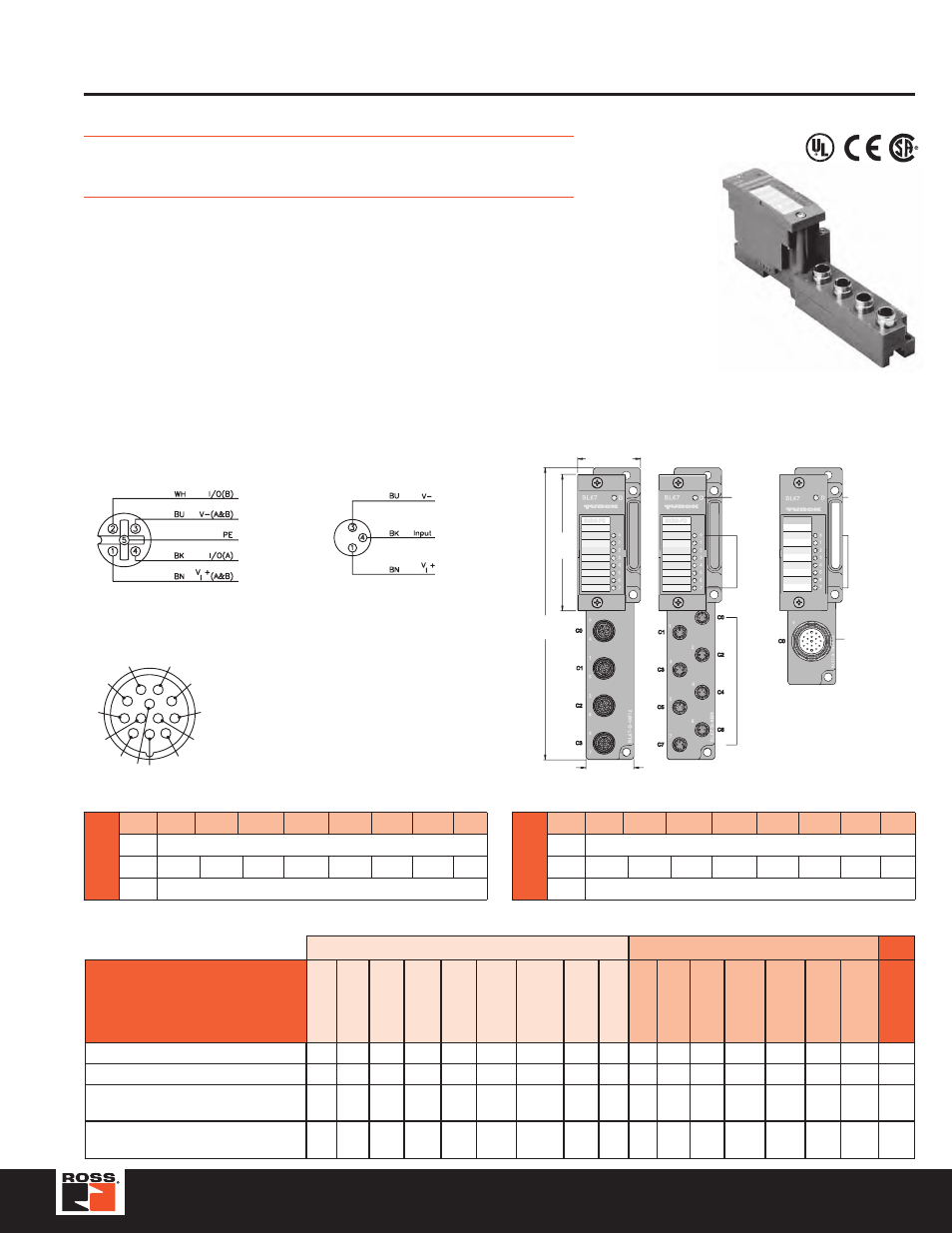
BL67-8XSG-P
BL67-8XSG-PD
C
A
B
3.583
(91.0)
1.654 (42.0)
Diagnostic
LEDs
I/O
LEDs
I/O
Connectors
1.260 (32.0)
7.677
(195.0)
Diagnostic
LEDs
I/O LEDs
I/O
Connectors
Inputs
Outputs
Data
Part Number
Dra
wing
Input Count
Connector
s
Pinout
Inputs per
Connector
Sensor
Style
V
I
+ A
v
ail.
Current
Individual
Dia
gnostics
Wire-Break
Detection
Output Count
Connector
s
Pinout
Outputs per
Connector
Current
Individual
Dia
gnostics
Wire-Break
Detection
I/O
Map
BL67-8XSG-PD with BL67-B-4M12*
A
8
0-3
2X
2
PNP
X
8
0-3
2X
2
0.5 A X
1
BL67-8XSG-PD with BL67-B-8M8*
B
8
0-7
PI
1
PNP
X
8
0-7
PO
1
0.5 A X
1
BL67-8XSG-PD with BL67-B-1M23
C
8
0
M23
8
PNP
80 mA
each
8
0
M23
8
0.5 A X
1
BL67-8XSG-PD with BL67-B-1M23-VI*
C
8
0
M23
8
PNP
4A
total
8
0
M23
8
0.5 A X
1
M23
1 = Output
0
2 = Output
1
3 = Output
2
4 = Output
3
5 = Output
4
6 = Output
5
7 = Output
6
8 = Output
7
9 = V
I
+
10 = V
I
+
11 = V
I
+
12 = V-
1
4
3
5
2
6
7
8
9
10
11
12
I/O Data Map 1
Shown with
BL67-B-4M12 base
Input/Output Connectors
2X
Mating cordset: RK 4.4T-*-RS 4.4T
Splitter:
VBRS 4.4-2RK 4T-*/*
PI
Mating cordset: PSG 3M-*
In
Byte
Bit 7
Bit 6
Bit 5
Bit 4
Bit 3
Bit 2
Bit 1
Bit 0
n-1
(Data for modules to the left)
n
I-7
I-6
I-5
I-4
I-3
I-2
I-1
I-0
n+1
(Data for modules to the right)
Out
Byte
Bit 7
Bit 6
Bit 5
Bit 4
Bit 3
Bit 2
Bit 1
Bit 0
n-1
(Data for modules to the left)
n
0-7
0-6
0-5
0-4
0-3
0-2
0-1
0-0
n+1
(Data for modules to the right)
I/O Data Map 1
Note: I/O faults can be reported in the I/O map. Consult the product user manual for details.
Modular I/O
•
Fieldbus Independent Configuration
•
IP 67 Protection
•
Various I/O Styles