Turck modular industrial i/o system bl 67, The bl67 solution, Bl67 power distribution – Ross Controls TURCK MODULAR I User Manual
Page 18: The bl67 concept, Maximum size of a bl67 station, Addressing, Power overview, Internal power consumption via module bus
18
© 2012,
ROSS
CONTROLS
®
.
All Rights Reserved.
The BL67 Solution
BL67 combines all the flexibility of an in-the-cabinet PLC I/O
system with modularity, ruggedness and connectorization.
BL67 complements the AIM™, BL20 and piconet
®
product
families to meet the needs of unique applications, such as small
machine or conveyor systems requiring IP 67 protection.
The BL67 Concept
The BL67 modular concept is a very flexible approach to
connectorized I/O. The gateway, base and electronic modules
provide many benefits to the user.
•
The gateway provides communication between the fieldbus
and I/O modules; modules are not dependent on the fieldbus
protocol.
•
DIN-rail or frame mountable base modules are available with
eurofast
®
(M12), minifast
®
(7/8-16UN), M23 and picofast
®
(M8) connectors.
•
Electronic modules are hot swappable.
•
Power distribution module (24 volts DC) supplies the
connected I/O signals.
BL67’s openness, flexibility, connectorization, compact
housing and ruggedness provide a viable alternative to in-
the-cabinet I/O.
Maximum Size of a BL67 Station
BL67 stations consist of a gateway and a maximum of 32
modules (equivalent to 1 m station length). Some high-tech and
analog I/O modules may consume or produce large amounts
of data, and therefore may limit the number of modules that
may be used per system. It is highly recommended that the I/
Oassistant software is used when planning and commissioning
BL67 systems. This program allows you to build the BL67 node
on your computer and verify that all restrictions with regard
to power and size are met. The free I/O assistant software is
available for download from www.turck.com.
Addressing
As a node on a network, BL67 stations are addressed
dependent on the network system being used. Each network
gateway has a set of rotary switches used to set the address
for the node. DeviceNet™ and CANopen gateways may be
addressed between 0 and 63 via two switches (one for the 10’s
digit and one for the 1’s digit). For example, to set the address
to 37 you would set the 10’s switch to 3 and the 1’s switch to
7. The third switch on the gateway may be used to set the
communication rate of the network interface. PROFIBUS
®
-DP
gateways may be set from 1 to 125 by using three switches
(one for the 100’s, one for the 10’s and one for the 1’s).
Ethernet gateways allow different addressing schemes
depending on the Ethernet addressing method being used
in the overall system. Dynamic addressing schemes include
BootP and DHCP, while hard-coding a static address is also
allowed.
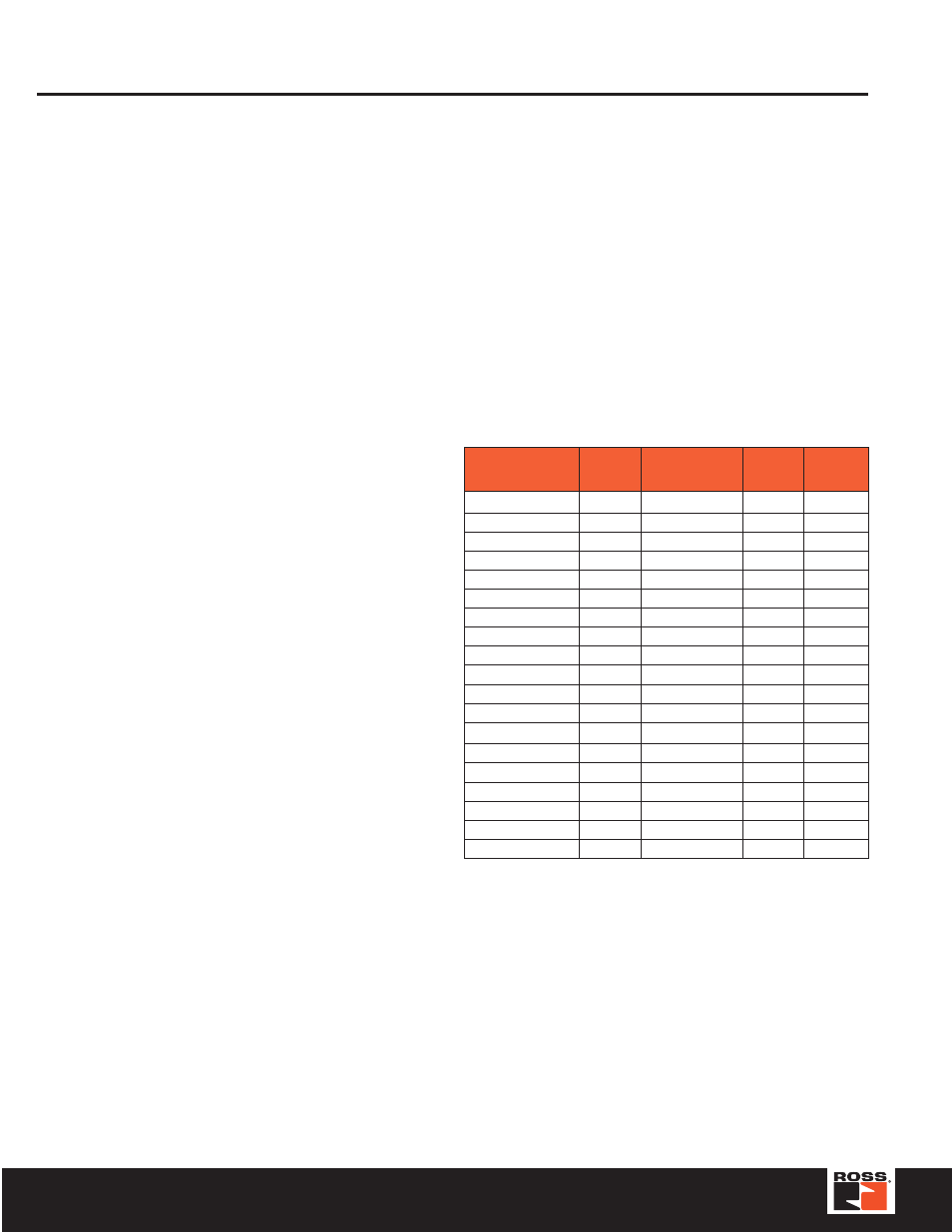
TURCK Modular Industrial I/O System BL 67
Module
Nominal 1
Current
at 5 V I
MB
Effective Draw 2
from Gateway at
24 VDC I
MB(24)
Nominal 3
Current
from V
I
Nominal 4
Current
from V
O
BL67-GW-DPV1
–
≤
150 mA
BL67-GW-DN
–
≤
100 mA
BL67-PF-24VDC
≤
30 mA
≤
9 mA
BL67-4DI-P
≤
30 mA
≤
9 mA
≤
40 mA
BL67-8DI-P
≤
30 mA
≤
9 mA
≤
40 mA
BL67-4DO-0.5A-P
≤
30 mA
≤
9 mA
≤
100 mA
BL67-4DO-2A-P
≤
30 mA
≤
9 mA
≤
100 mA
BL67-8DO-0.5A-P
≤
30 mA
≤
9 mA
≤
100 mA
BL67-2AI-V
≤
35 mA
≤
10 mA
≤
12 mA
BL67-2AI-I
≤
35 mA
≤
10 mA
≤
12 mA
BL67-2AI-TC
≤
35 mA
≤
10 mA
≤
30 mA
BL67-2AI-PT
≤
45 mA
≤
13 mA
≤
45 mA
BL67-2AO-I
≤
40 mA
≤
12 mA
≤
50 mA
BL67-2AO-V
≤
60 mA
≤
17 mA
≤
50 mA
BL67-1RS232
≤
100 mA
≤
28 mA
≤
50 mA
BL67-8XSG-PD
≤
30 mA
≤
9 mA
≤
100 mA
BL67-1SSI
≤
50 mA
≤
15 mA
≤
50 mA
BL67-4DI-PD
≤
30 mA
≤
9 mA
≤
100 mA
BL67-8DI-PD
≤
30 mA
≤
9 mA
≤
100 mA
To calculate current draw on DeviceNet: Add IMB(24) for all
modules. Then add VI and VO for electronic modules to the left
of the first power feed module. Next, add the current draw of
the I/O devices.
To calculate current draw on PROFIBUS gateway power
connector for VI: Add IMB for all modules. Then add VI current
for all modules to the left of the first power feed module. Next,
add the current draw of the input devices.
For VO, add the VO current for all modules to the left of the first
power feed module. Next, add the current draw of the output
devices.
VMB = Module bus power
VI = Input power
VO = Output power
IMB = Module bus current
IMB(24) = Effective current draw from gateway at 24 volts DC supply
BL67 Power Distribution
Power Overview
The power supply for a BL67 station is fed via the power
connector on the PROFIBUS
®
gateway or directly from the
network on the DeviceNet™ gateway. Power feeder modules
can be added to the system at any point to provide a fresh
isolated supply of power to all I/O connected to its right.
Internal Power Consumption via Module Bus
The amount of BL67 modules that may be supplied via the
internal module bus depends on the respective nominal current
IMB of the individual modules on the module bus. The sum of
the nominal current inputs of the connected BL67 module must
not exceed 1.5 A. If the I/O assistant software is used, an error
message is generated automatically via the
as soon as the system supply via the module bus is no longer
sufficiently guaranteed.