5 internal peripheral device connections, 1 sata drive connection, Nternal – IEI Integration IMBA-G410 v2.00 User Manual
Page 68: Eripheral, Evice, Onnections, Figure 4-13: usb power select jumper location, Table 4-7: usb power select jumper settings, Ee table 4-7, Ee figure 4-13
541/20/2012165
P a g e 54
IMBA-G410 ATX Mo th e rb o a rd
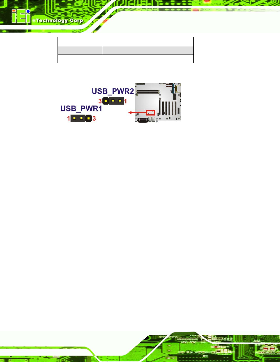
Setting
Description
Short 1-2
+5 V (Default)
Short 2-3
+5VSB
Table 4-7: USB Power Select Jumper Settings
Figure 4-13: USB Power Select Jumper Location
4.5 In te rn a l P e rip h e ra l De vic e Co n n e c tio n s
This section outlines the installation of peripheral devices to the onboard connectors.
4.5.1 S ATA Drive Co n n e c tio n
The IMBA-G410 is shipped with two SATA drive cables and one SATA drive power cable.
To connect the SATA drives to the connectors, please follow the steps below.
S te p 1:
Locate the connectors. The locations of the SATA drive connectors are shown
in Chapter 3.
S te p 2:
Insert the cable connector. Press the clip on the connector at the end of the
SATA cable and insert the cable connector into the on-board SATA drive
connector. See Figure 4-14.