4 chassis installation, 1 airflow, 2 cpu card installation – IEI Integration PCIE-H610 User Manual
Page 64: 5 internal peripheral device connections, Hassis, Nstallation, Nternal, Eripheral, Evice, Onnections
PCIE-H610 PICMG 1.3 CPU Card
Page 49
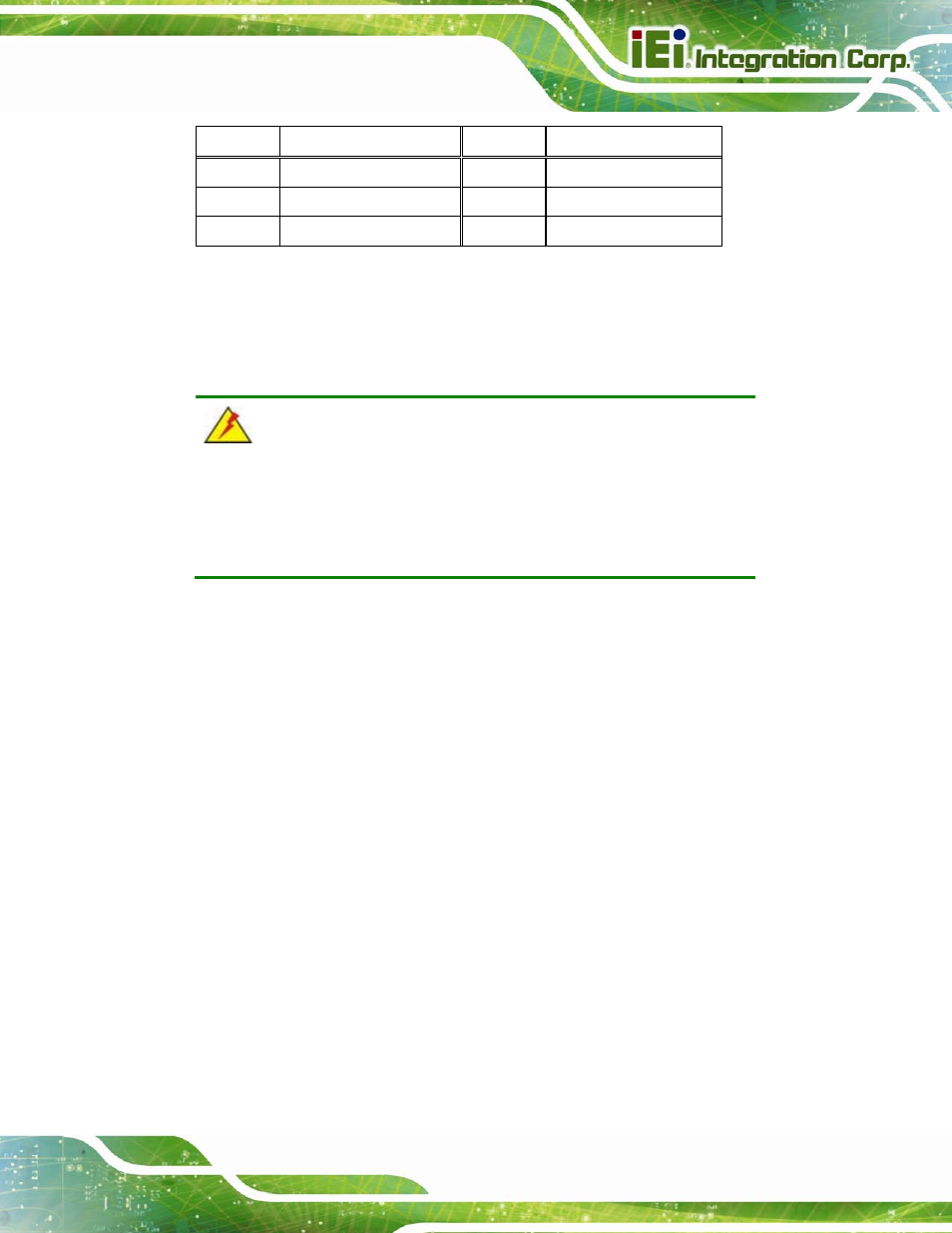
Pin Description
Pin Description
1
+3.3V_DUAL
2
+3.3V_DUAL
3
+V3.3LAN2
4
+V3.3LAN1
5
+3.3V
6
+3.3V
Table 4-5: Wake-on LAN Jumper Pinouts
4.4 Chassis Installation
4.4.1 Airflow
WARNING:
Airflow is critical to the cooling of the CPU and other onboard
components. The chassis in which the PCIE-H610 must have air vents
to allow cool air to move into the system and hot air to move out.
The PCIE-H610 must be installed in a chassis with ventilation holes on the sides allowing
airflow to travel through the heat sink surface. In a system with an individual power supply
unit, the cooling fan of a power supply can also help generate airflow through the board
surface.
4.4.2 CPU Card Installation
To install the CPU card onto the backplane, carefully align the CPU card edge connector
with the CPU card socket on the backplane. To do this, please refer to the reference
material that came with the backplane. Next, secure the CPU card to the chassis. To do
this, please refer to the reference material that came with the chassis.
4.5 Internal Peripheral Device Connections
This section outlines the installation of peripheral devices to the onboard connectors.