1 peripheral interface connectors, 1 pcie-h610 layout, 2 peripheral interface connectors – IEI Integration PCIE-H610 User Manual
Page 31: Eripheral, Nterface, Onnectors, Figure 3-1: connectors and jumpers
PCIE-H610 PICMG 1.3 CPU Card
Page 16
3.1 Peripheral Interface Connectors
This chapter details all the jumpers and connectors.
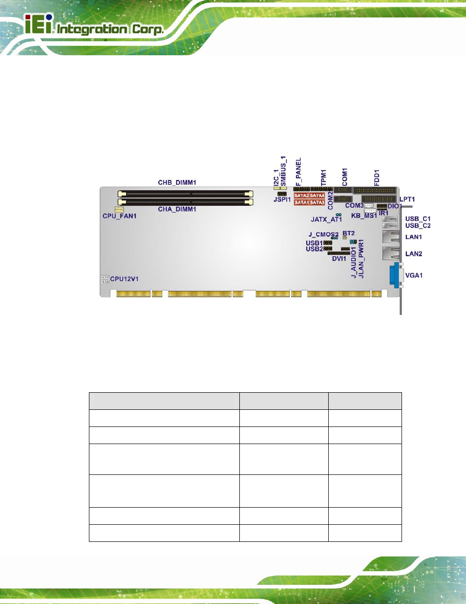
3.1.1 PCIE-H610 Layout
The figures below show all the connectors and jumpers.
Figure 3-1: Connectors and Jumpers
3.1.2 Peripheral Interface Connectors
The table below lists all the connectors on the board.
Connector
Type
Label
Audio kit connector
10-pin header
J_AUDIO1
Battery connector
2-pin wafer
BT2
CPU power input connector
4-pin Molex power
connector
CPU12V1
DDR3 DIMM sockets
240-pin socket
CHA_DIMM1
CHB_DIMM1
Digital I/O connector
10-pin header
DIO1
DVI-D connector (DVI model only)
26-pin header
DVI1
See also other documents in the category IEI Integration Hardware:
- SPCIE-5100DX (180 pages)
- SPCIE-C2060 v1.01 (200 pages)
- SPCIE-C2060 v2.12 (212 pages)
- SPCIE-C2160 (204 pages)
- SPCIE-C2260-i2 (217 pages)
- ROCKY-3786 v4.0 (175 pages)
- ROCKY-3786 v4.10 (147 pages)
- PCIE-Q350 v1.00 (272 pages)
- PCIE-Q350 v1.12 (250 pages)
- PCIE-Q350 v1.20 (250 pages)
- PCIE-Q350 v1.30 (213 pages)
- PCIE-Q57A (159 pages)
- PCIE-G41A2 (151 pages)
- PCIE-Q670 v1.03 (206 pages)
- PCIE-Q670 v2.00 (205 pages)
- PCIE-Q870-i2 (217 pages)
- IOWA-LX-600 (159 pages)
- PCISA-945GSE v1.01 (207 pages)
- PCISA-945GSE v1.10 (190 pages)
- PCISA-9652 v1.00 (232 pages)
- PCISA-9652 v1.01 (232 pages)
- PCISA-PV-D4251_N4551_D5251 (145 pages)
- PICOe-945GSE (197 pages)
- PICOe-GM45A (198 pages)
- PICOe-PV-D4251_N4551_D5251 v1.00 (154 pages)
- PICOe-PV-D4251_N4551_D5251 v1.10 (154 pages)
- PICOe-PV-D4251_N4551_D5251 v1.11 (155 pages)
- PICOe-B650 (156 pages)
- PICOe-HM650 (174 pages)
- HYPER-KBN (139 pages)
- SPXE-14S (3 pages)
- SPXE-9S v1.00 (5 pages)
- SPXE-9S v1.1 (6 pages)
- SPE-9S v1.00 (4 pages)
- SPE-9S v1.1 (5 pages)
- SPE-6S (3 pages)
- SPE-4S (4 pages)
- PE-6SD3 (4 pages)
- PE-6SD2 v4.0 (4 pages)
- PE-6SD2 v2.10 (3 pages)
- PE-6SD (3 pages)
- PE-6S3 v1.0 (2 pages)
- PE-6S3 v4.0 (4 pages)
- PE-6S2 (4 pages)