Warner Electric SFC-120, SFC-170, SFC-250, SFC-400 Bearing Mounted, Flange Mounted User Manual
Page 6
6
Warner Electric • 800-825-9050
P-200
• 819-0481
SF-400
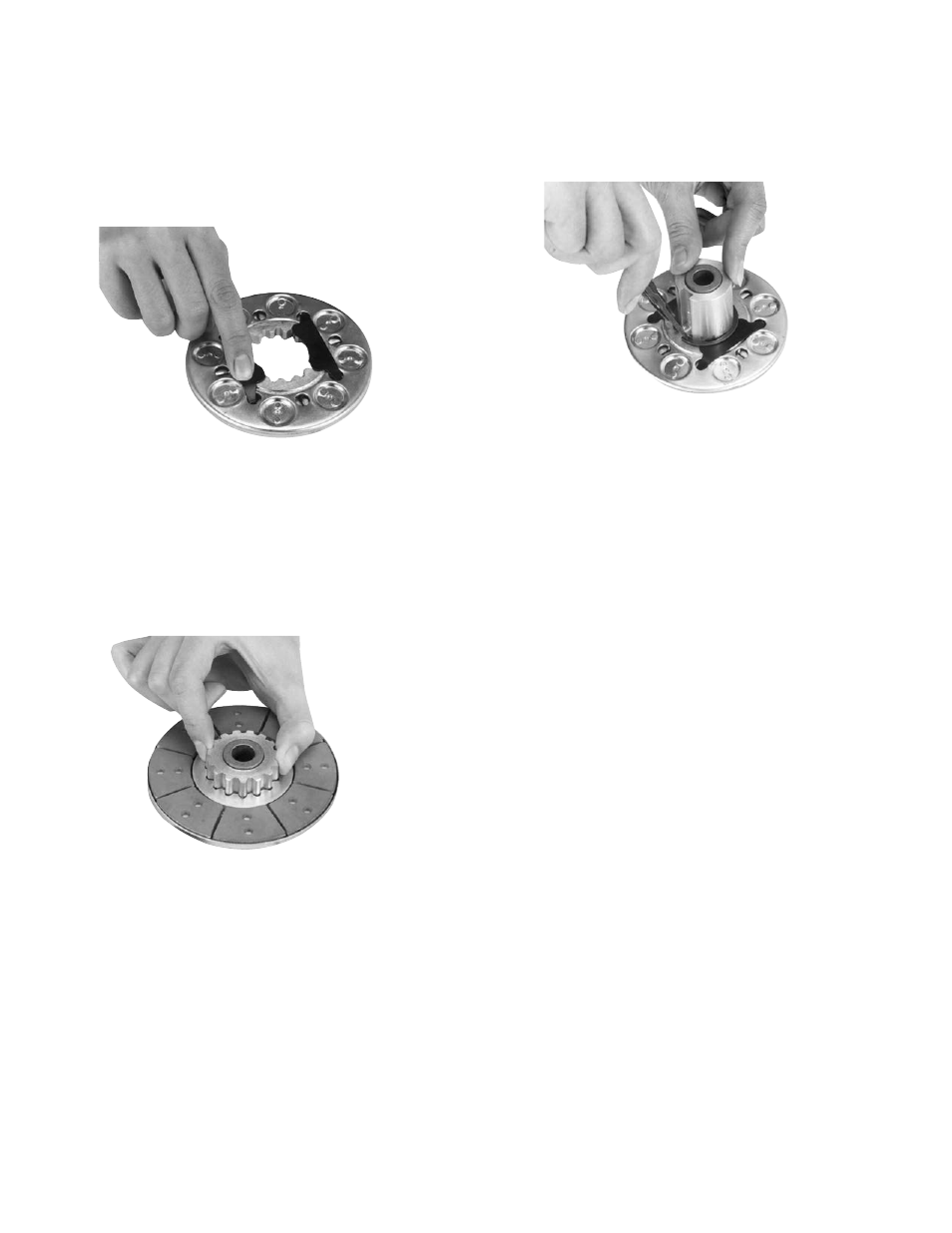
Insert the release springs into the backing plate
holes of the armature. Bow the springs as nec-
essary to insert them into the armature. (See
Figure 7)
Remove the snap ring from the hub.
Insert the hub, with the setscrew end first, into
the armature from the segmented side. Slide
the hub into the armature until the release
springs engage the snap ring groove. (See
Figure 8)
Assemble the snap ring into the groove in the
hub, clamping the release spring against the
end of the spline. (See Figure 9)
D. Mounting the Armature Assembly
1. Slide the armature assembly onto the shaft.
Position the assembly in accordance with the
overall axial dimensions given on the illustration
drawings.
2. The armature-hub assembly can be held in this
position with retainer rings, a set collar, a
shoulder on the shaft, or any combination of
these. The hub may need to be repositioned as
wear occurs with time.
Figure 7
Figure 8
Figure 9