Warner Electric SFC-120, SFC-170, SFC-250, SFC-400 Bearing Mounted, Flange Mounted User Manual
Page 41
41
Warner Electric • 800-825-9050
P-200
• 819-0481
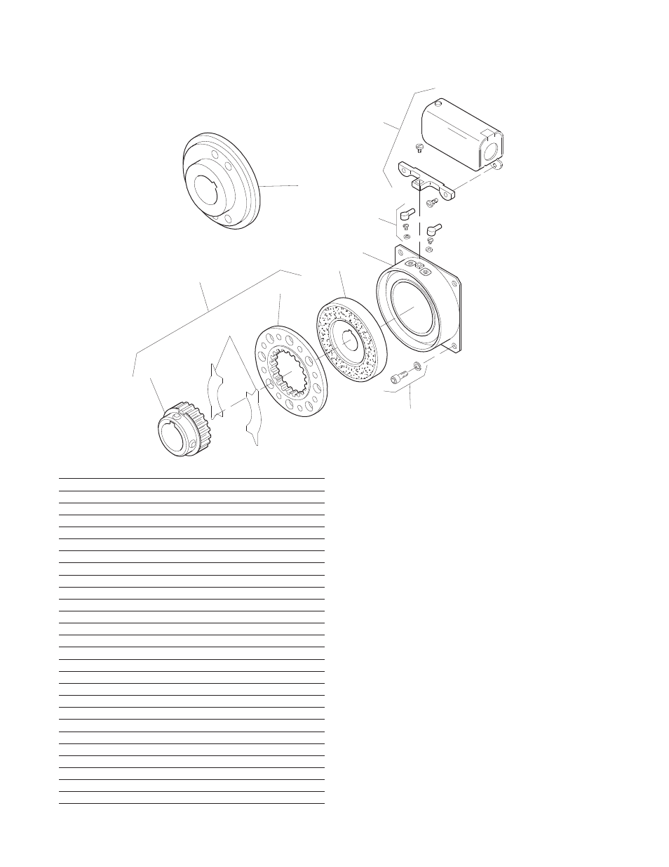
1A-1
1A-3
1A
1A-2
2
3
5
3-1
4
1B
How to Order:
1. Specify Type of Armature Desired.
2. Specify Bore Size for Item 1A-1 or 1B and Item 2.
3. Specify Voltage for Item 3.
Example:
SFC-400 Clutch Coupling per I-25697 - 90 Volt
3/4" Armature Hub Bore
3/4" Rotor Bore
These units, when used in conjunction with the correct
Warner Electric conduit box, meet standards set forth in
UL508 and are listed under guide card #NMTR2, file
#59164.
These units are CSA certified under file #LR11543.
Item
Description
Part Number
Qty.
1A
Armature and Hub
1A-1
Armature Hub
1
1/2" Bore
5104-541-002
5/8" Bore
5104-541-004
3/4" Bore
5104-541-006
7/8" Bore
5104-541-007
1A-2
Armature
5125-111-001
1
1A-3
Release Spring
5104-101-003
1
1B
Antibacklash Armature
1
1/2" Bore
5367-111-003
5/8" Bore
5367-111-005
3/4" Bore
5367-111-007
7/8" Bore
5367-111-008
2
Rotor
1
1/2" Bore
5104-751-033
5/8" Bore
5104-751-034
3/4" Bore
5104-751-035
7/8" Bore
5104-751-036
1" Bore
5104-751-037
3
Field
1
6 Volt
5104-451-032
24 Volt
5104-451-033
90 Volt
5104-451-034
3-1
Terminal Accessory
5103-101-002
1
4
Conduit Box
5200-101-010
1
5
Mounting Accessory
5104-101-002
1
SFC-400 Clutch Coupling Flange Mounted – Outside Mounted
Drawing I-25697