Warner Electric SFC-120, SFC-170, SFC-250, SFC-400 Bearing Mounted, Flange Mounted User Manual
Page 22
22
Warner Electric • 800-825-9050
P-200
• 819-0481
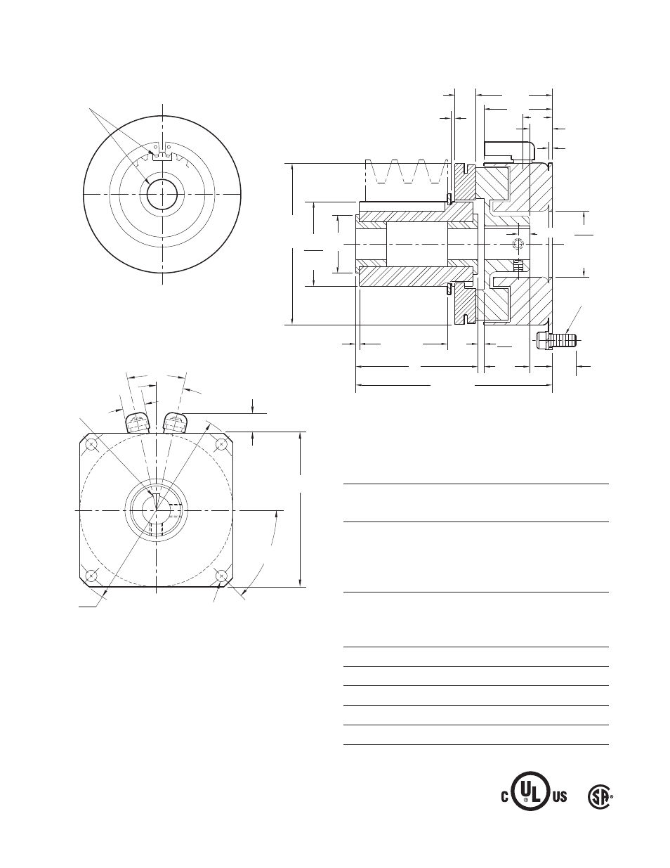
.135
*
.095
8-32 UNC-
3A
.015 When New
.343 Max.
1.125
.468
.380/.370
.062
.062
2
.437
Max.
.171
1.063
1.061
Pilot
Dia.
1.453 Min.
3.281 Max.
.750
2.625
Max. Dia.
1.376
1.375
Dia.
.750
Dia.
1.250
SF-250 Clutch Flange Mounted
Bore and Keyway Dimensions
Armature
Keyway
Rotor
Keyway
Bore Dia.
Bore Dia.
.3750/.3745
.376/.375 .093 x .046
.5000/.4995 .312 x .156 *.438/.437 .125 x .031
*.5625/.5620
x 1.250
.501/.500 .125 x .031
.6250/.6245
*Available on special order only.
Customer Shall Maintain:
1. Squareness of field mounting face with shaft within
.003 T.I.R. measured at pilot diameter.
2. Concentricity of field mounting pilot diameter with
rotor mounting shaft within .003 T.I.R.
Armature Shaft
.375 – .625
Rotor Shaft
.375 – .500
Static Torque
70 lb.in.
Maximum Speed
7,500 rpm
Standard Voltage
D.C. 6, 24, 90
All dimensions are nominal unless otherwise noted.
Armature View
For Bore & Keyway sizes
see chart below.
Field View
For Bore & Keyway
sizes see chart
below.
45°
3.500
3.498
Pilot Dia.
.204/.187 dia. (4) holes
equally spaced on 3.125
dia.*
2.625 Sq.
24°
12°
.437
.437
*Customer shall maintain dimension as noted.
*Mounting holes are within .010 of true position relative to pilot diameter.