Sfc-400 clutch coupling flange mounted, Bore and keyway dimensions – Warner Electric SFC-120, SFC-170, SFC-250, SFC-400 Bearing Mounted, Flange Mounted User Manual
Page 40
40
Warner Electric • 800-825-9050
P-200
• 819-0481
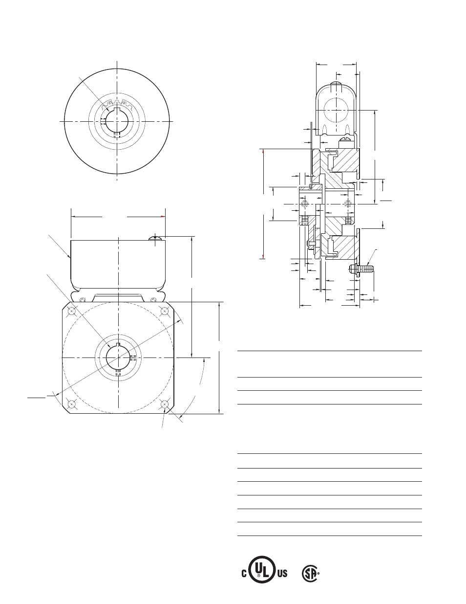
SFC-400 Clutch Coupling Flange Mounted
Armature Shaft
.500 – .875
Rotor Shaft
.500 – 1
Static Torque
270 lb. in.
Maximum Speed
4,500 rpm
Standard Voltage
D.C. 6, 24, 90
All dimensions are nominal unless otherwise noted.
Bore and Keyway Dimensions
Armature
Keyway
Rotor
Keyway
Bore Dia.
Bore Dia.
.501/.500 .125 x .062
.501/.500
.125 x.062
*.563/.562
.626/.625
.626/.625
*.688/.687 .187 x .093
.751/.750 .187 x .093
.751/.750
.876/.875
.876/.875
1.001/1.000
*Available on special order only
Armature View
*Mounting holes are within .010 of true position relative to pilot diame-
ter.
Field View
1.875
1.873
Pilot Dia.
1/4-20
UNC-3A
1.250
(Std.)
.328
.015
.671
3.562
.609 Max.
.328 Max.
.015 When New
.187 (Std.)
.218 (Anti.)
.250
.093
1.640
(Anti.)
1.546
.937
.875
4.234
Max.
Dia.
.187 (Std.)
.218 (Anti.)
.828
1.312
1.500
1.50
2.328/2.359
.192/.182
1.125
Antibacklash
Arm.
Std. Arm.
For Bore & Keyway sizes
see chart below.
For Bore
& Keyway
sizes see
chart
below.
Removabl
e plug in
ends for
1/2"
conduit.
45°
5.626
5.623
Pilot Dia.
.296/.280 dia. (4) holes equally spaced on 5.000 dia.*
4.250 Sq.
4.687
3.750
Customer Shall Maintain:
1. Squareness of field mounting face with rotor shaft
within .003 T.I.R. measured at pilot
diameter.
2. Concentricity of field mounting pilot diameter with
rotor mounting shaft within .003 T.I.R.
3. Rotor and armature shafts in line within .003 T.I.R.