Sf-400 clutch flange mounted, Bore and keyway dimensions – Warner Electric SFC-120, SFC-170, SFC-250, SFC-400 Bearing Mounted, Flange Mounted User Manual
Page 24
24
Warner Electric • 800-825-9050
P-200
• 819-0481
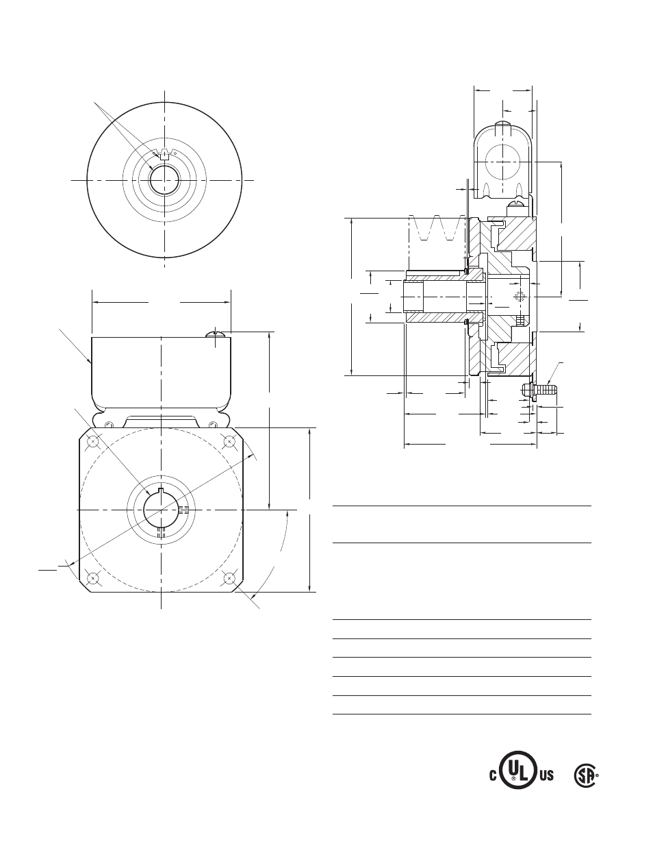
SF-400 Clutch Flange Mounted
Customer Shall Maintain:
1. Squareness of field mounting face with shaft within
.003 T.I.R. measured at pilot diameter.
2. Concentricity of field mounting pilot diameter with
rotor mounting shaft within .003 T.I.R.
*3. Customer shall maintain dimension as noted.
Bore and Keyway Dimensions
Armature
Keyway
Rotor
Keyway
Bore Dia.
Bore Dia.
.5000/.4995 .312 x .156 .501/.500 .125 x.062
.6250/.6245
x 1.25
.626/.625
.7500/.7495
.751/.750 .187 x .093
Armature Shaft
.500 – .750
Rotor Shaft
.500 – 1
Static Torque
270 lb.in.
Maximum Speed
4,500 rpm
Standard Voltage
D.C. 6, 24, 90
All dimensions are nominal unless otherwise noted.
Armature View
Field View
For Bore & Keyway
sizes see chart below.
Removable plug
in ends for 1/2"
conduit.
.296/.280 dia. (4) holes equally spaced on
5.000 dia. Mounting holes are within .010 of
true position relative to pilot diameter.
45°
5.625
5.623
Pilot
Dia.
4.250
Sq.
3.750
4.687 Max.
1.875
1.873
Pilot Dia.
4.234
Max. Dia.
1.376
1.375
Dia.
.875
Dia.
.328 Max.
1.500
1.312
.015 When New
.192/.182
.093
.250
.062
1.468
Min.
2.125
3.546 Max.
1.125
.609 Max.
1/4-20 UNC-
3A
.082
.042
1.546
.937
3.562
For Bore &
Keyway
sizes see
chart
below.
*