Warner Electric SFC-120, SFC-170, SFC-250, SFC-400 Bearing Mounted, Flange Mounted User Manual
Page 10
10
Warner Electric • 800-825-9050
P-200
• 819-0481
D. Mounting the Armature Assembly
1. SFC 250 and 400 size units.
Insert a key in the keyslot of the shaft and slide the
armature assembly onto the shaft.
2. (SFC120 do not use keyway)
Position the assembly to allow a gap of about 1/64
inch between the faces of the armature and magnet.
The overall axial dimension should be in accordance
with the dimensions specified on the illustration
drawings.
3. Secure the assembly in this position by alternately
tightening the two setscrews in the hub.
4. The hub may need to be repositioned as wear
occurs with time.
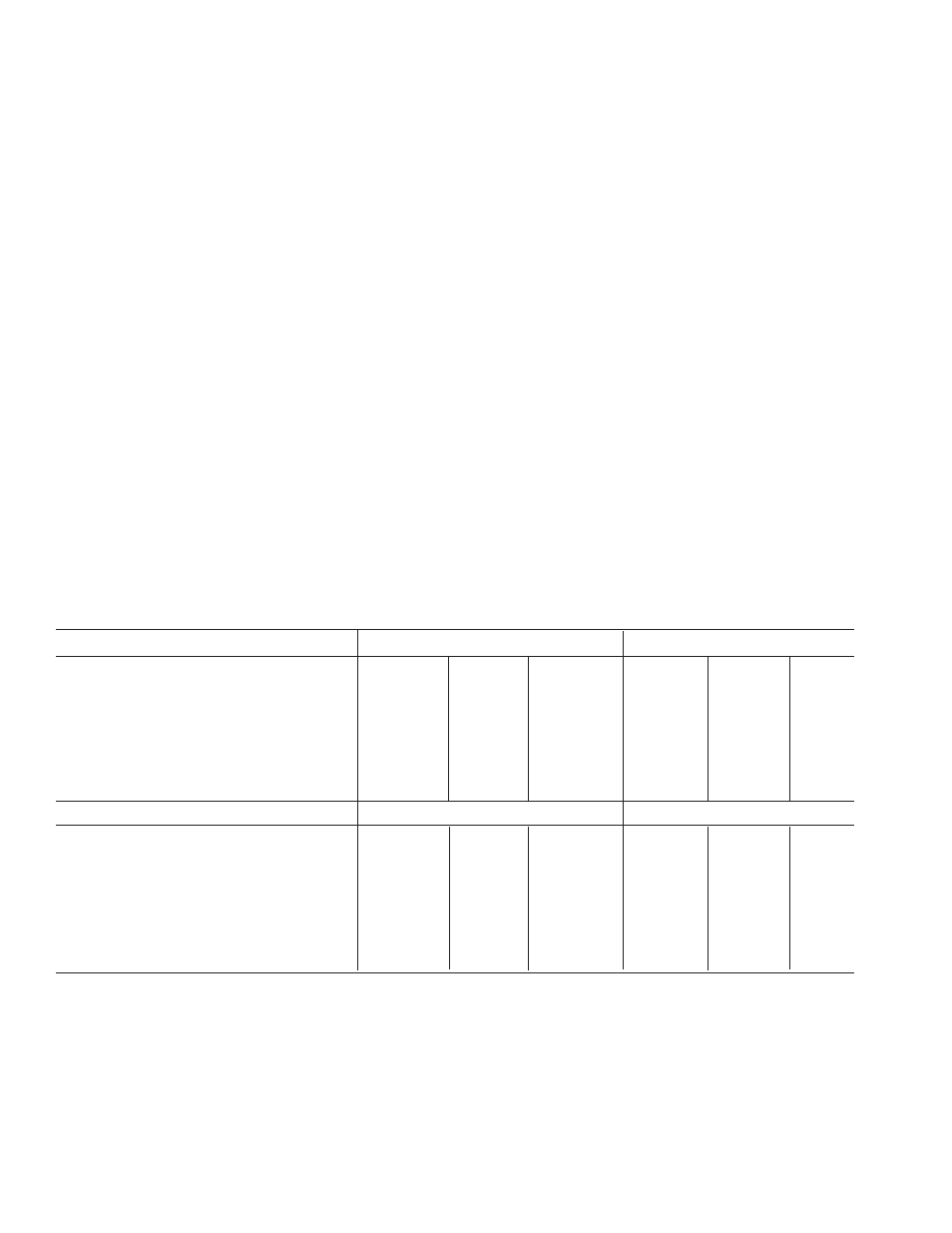
Electrical Coil Data
Unit Size
SF/SFC 120
SF/SFC 170
Voltage – DC
6
24
90
6
24
90
Resistance @ 20°C — Ohms
6.32
104
1386
6.96
111.2
1506
Current — Amperes
.949
.230
.065
.861
.215
.060
Watts
5.69
5.52
5.85
5.85
5.16
5.37
Coil Build-up — Milliseconds
12
12
11
17
17
16
Coil Decay — Milliseconds
8
8
7
8
7
6
Unit Size
SF/SFC 250
SF/SFC 400
Voltage – DC
6
24
90
6
24
90
Resistance @ 20°C — Ohms
5
76.4
1079
4.88
73
1087
Current — Amperes
1.2
.314
.084
1.23
.322
.083
Watts
7.2
7.5
7.51
7.39
7.96
7.45
Coil Build-up — Milliseconds
48
48
44
154
154
154
Coil Decay — Milliseconds
15
15
13
62
60
55
Notes: Build-up time equals current to approximately 90% of steady state value and flux to 90%.
Decay time equals current to approximately 10% of steady state value and flux to 10%.
Approximately because current leads or lags flux by a small amount.