Teledyne LeCroy PETracer Summit and Summit T2-16 PCIe User Manual User Manual
Page 43
Summit User Manual
Chapter 3: Installation and Setup
Teledyne
LeCroy
35
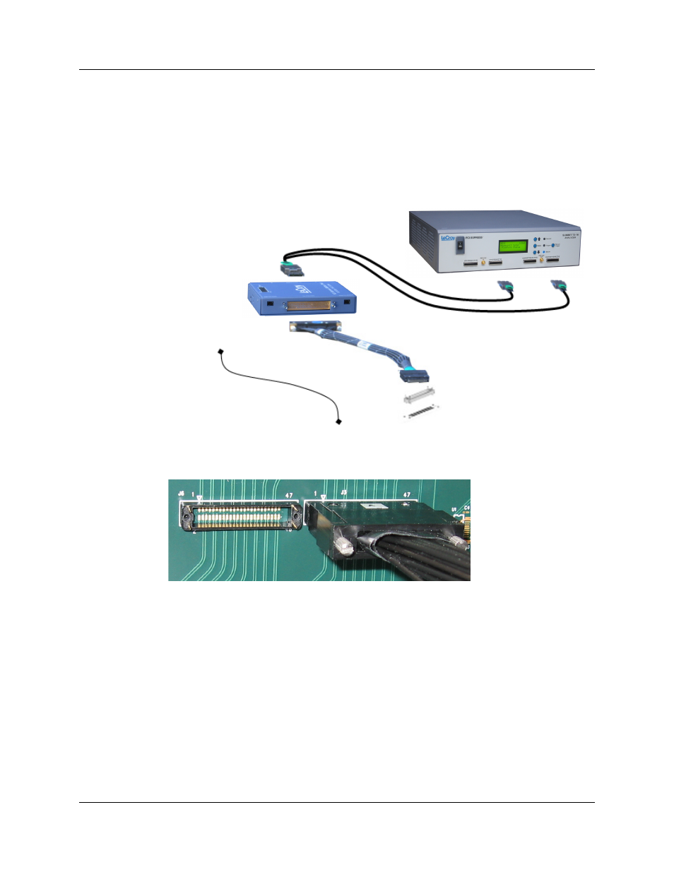
Connections Overview for Gen2 MidBus Probe
Use a 1-pod or 2-pod setup depending on the lane width of the recording:
•
For x16 recordings, use the 2-pod setup.
•
For all other lane width recordings, use a one-pod setup.
Use the iPass Y-cables to connect the probe data connectors on the Analyzer to the
MidBus pod(s).
On the other side of the pod, connect the MidBus probe assembly.
Connect the header on the MidBus probe assembly to the MidBus footprint on the
System Under Test (host platform/root complex). The following picture shows two midbus
footprints, with one connected to the MidBus probe assembly:
Connection Procedure
To connect the Summit T2-16 to the System Under Test (host platform/root complex):
Step 1 Connect the MidBus pods to the Analyzer using the iPass Y-cables.
Step 2 Connect the MidBus probe assemblies to the MidBus pods.
Step 3 Connect the MidBus probe assemblies to the MidBus footprints on the system
under test.
Step 4 Connect external reference clock signal to Mid-Bus External Clock In on
Mid-Bus probe pod, using external reference clock cable. For x16, you
need to chain the pods.