6 petracer summit rear panel description – Teledyne LeCroy PETracer Summit and Summit T2-16 PCIe User Manual User Manual
Page 26
Chapter 2: Hardware Description
Summit User Manual
18
Teledyne
LeCroy
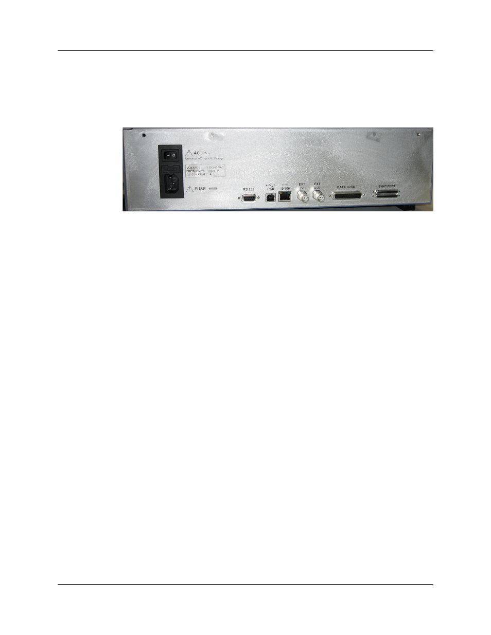
2.6 PETracer Summit Rear Panel Description
From left to right, the PETracer Summit rear panel contains the following components:
Figure 2.2 PETracer Summit Rear Panel
Wide-range AC Connector Module
•
Power socket
•
Enclosed 5x20 mm 2.0A 250 V fast acting glass fuse
•
Power on/off switch
Warning! For continued protection against fire, replace fuse only with the type and
rating specified above.
RS-232 25-pin Data Input/Output Connector
This connector links a 25 pin RS-232 cable to an external Breakout Board. The
Breakout Board allows signals to be sent from the Analyzer to an external device such
as an oscilloscope or from an external device to the Analyzer for the purpose of triggering
on an external input. You configure input/output signalling through the Recording Options
dialog box. The Breakout Board use is described at the end of this chapter.
USB Type B Host Machine Connector
This connector links the Analyzer to the host machine for the purpose of transmitting
commands from the host machine to the Analyzer and uploading traces from the
Analyzer’s recording memory to the PETracer software for viewing and analysis. Note:
May not be active on some Summit systems.
Ethernet Port
10/100 Mbps Ethernet Connectivity allows connection to an Ethernet network and
sharing of analyzer resources by multiple engineers.