Pin-outs for the data in/out connector, Prototype rework area – Teledyne LeCroy PETracer Summit and Summit T2-16 PCIe User Manual User Manual
Page 29
Summit User Manual
Chapter 2: Hardware Description
Teledyne
LeCroy
21
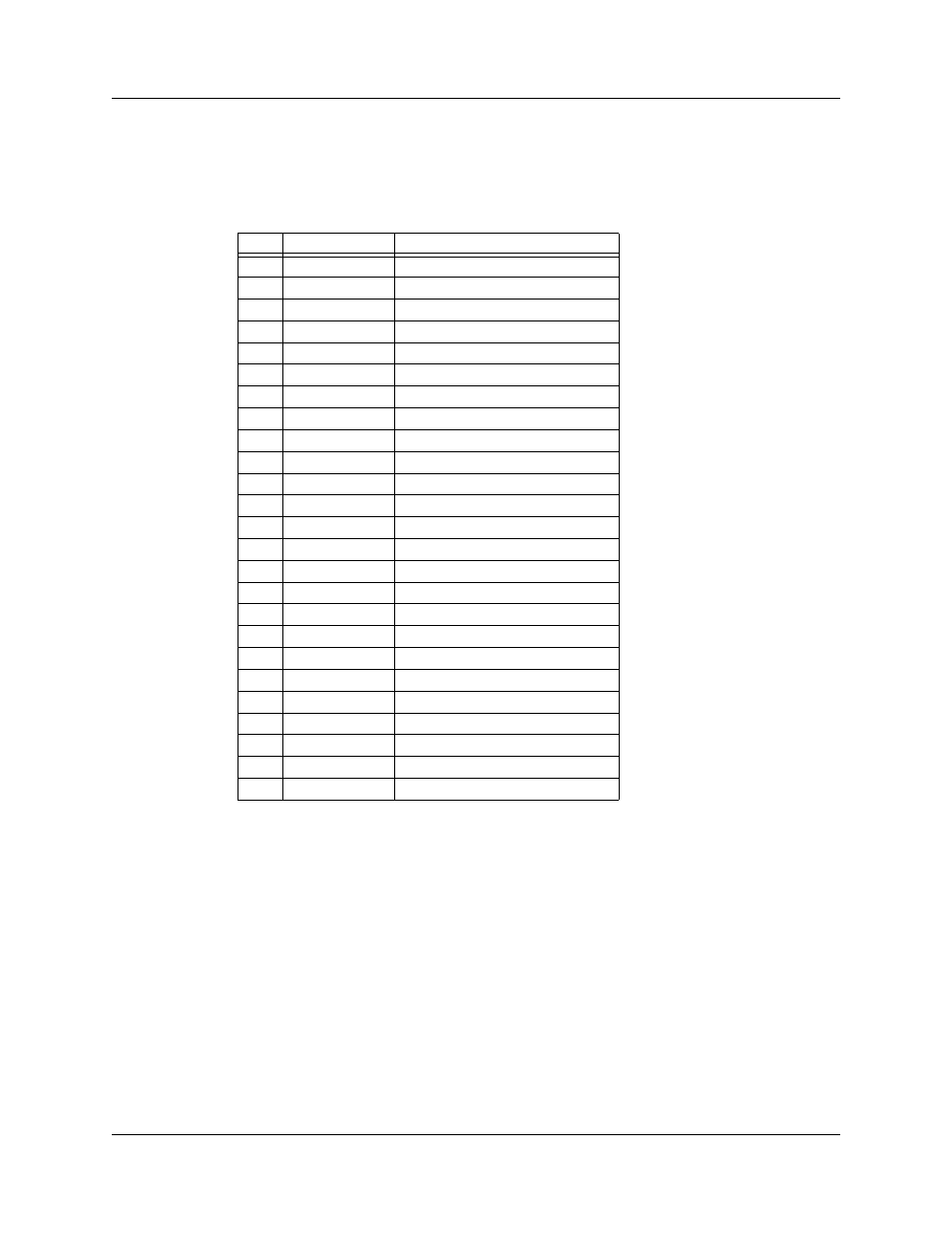
Pin-Outs for the Data In/Out Connector
The following table lists the pin-out and signal descriptions for the Data In/Out connector
on a cable that connects to the Breakout Board.
Data In/Out Connector – Pin-Out
Note:
(*)
Pins 4 and 17 have the same function: they allow external signals to be
used to cause triggering or recording. Pins 3 and 16 are used to transmit
output signals. Pins 6, 7, 8, 9, 18, 19, 21, and 22 (data pins) are used to
define data patterns for external input signals.
Note: All models of PETracer only support Data 0 - Data 3.
Prototype Rework Area
The Breakout Board contains a prototype rework area for making custom circuits for rapid
development. The area consists of plated-through holes, 20 columns wide by 27 rows
long. The top row of holes is connected to GND and the bottom row is connected to +5V.
The remaining holes are not connected. Use the rework area to insert custom
components and wire-wrap their respective signal, power, and ground pins.
Pin
Signal Name
Signal Description
1
RSV
Reserved
2
GND
Ground
3
GP OUT
General Purpose Output
4
TRG IN 1
Trigger In 1
5
GND
Ground
6
DATA 6
Data 6
7
DATA 4
Data 4
8
DATA 3
Data 3
9
DATA 1
Data 1
10
GND
Ground
11
RSV
Reserved
12
RSV
Reserved
13
+5V
+5 Volts, 250 mA DC Source
14
RSV
Reserved
15
GND
Ground
16
TRG OUT
Trigger Out
17
TRG IN 0
Trigger In 0
18
DATA 7
Data 7
19
DATA 5
Data 5
20
GND
Ground
21
DATA 2
Data 2
22
DATA 0
Data 0
23
GND
Ground
24
RSV
Reserved
25
RSV
Reserved