Ir application diagrams – Staub Electronics B-500-MTRX-230-8X8 BINARY - HDMI 8X8 MATRIX SWITCH WITH HDMI AND HDBASET OUTPUTS User Manual
Page 14
B-500-MTRX-230-8x8 Installation Manual
Pg. 14
© 2013 Binary
™
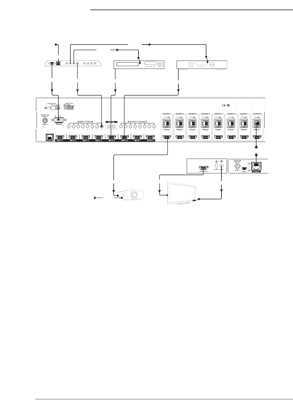
7.10. IR Application Diagrams
7.10.1. IR Pass-Through from Control System
The diagram above illustrates a typical installation with a B-500-MTRX-230-8X8 where all of the equipment is being
controlled by a control system that uses RF (Radio Frequency) remotes in each output zone.
• The RF remotes transmit commands back to the control system which then sends commands to each device
being controlled. Custom programming by the installer sets the control system up to automatically switch inputs
and outputs in the matrix switcher as needed, so the end user only has to select the source they want to watch.
• Each display (only one is pictured for reference) requiring IR control is connected to the system via the HDBaseT
output of the matrix switcher. Cat5e/6 cable connects to a B-500-RX-230-IR Receiver, which is attached to the
display via HDMI for signal. An IR flasher connected to the IR flasher port sends the IR commands to the display.
Sources are directly controlled by the control system.
• IR control for displays is routed from the control system to the matrix switcher using 3.5mm mono mini cables
plugged into IR INPUT TO ROOM ports. The commands pass from a matrix switcher port to the HDBaseT output
of the same number. In the diagram the mono cable used to send commands to the output 8 zone is plugged into
IR INPUT TO ROOM port 8. This allows discrete control of each display connected, even if they are models with
the same codes.
• Some displays and projectors can be controlled by other methods than IR. The projector pictured features IP
control, so it is receiving commands from the control system over an Ethernet connection. An HDMI cable is
connecting it to the matrix switcher output since it is installed close enough to the equipment and requires no IR
flasher.
• When the system is in use, if two outputs are connected to the same input, the source will change on both outputs
with any command sent since it can’t send two HDMI streams at once. This must be considered when deciding on
the sources to connect for distribution.
Example: In a home with five displays connected, if users in every room want to watch satellite on
different channels, there must be five satellite receivers set up as sources. With custom programming,
each output can be programmed to use only one of the satellite source inputs, giving each output a
dedicated cable box, while allowing other less-used sources to connect to any output.
PWR
Engineered in the USA
Manufactured in Taiwan
IR IN ALL IR OUT
B-500-RX-230-IR
IR Outputs
RS232
IR Inputs
Projector
RS232 Cable
HDMI
HDMI
Cat5e/6
HDMI
PLAY
HDMI Source
256
HDMI
Source
IR Flasher
IR Flasher
3.5mm Mono
HDMI
HDTV
IR Flasher
Cat5e/6
Ethernet Connection
Cat5e/6
Ethernet Connection