KB Electronics KBDF-48 User Manual
Page 66
66
TABLE 14
IODF MULTI-FUNCTION INPUT TERMINAL, FUNCTION,
AND FACTORY CODE ASSIGNMENT
Multi-Function Input Terminal*
6 7
Number On Terminal Block
14 15
Function
7.05 7.06
Factory Code Setting
0003 0004
Code Description
Up Frequency Command
Down Frequency Command
*Each Multi-Function Input Terminal is controlled by a specific Function. Although factory set to
a specific code, they can also be reprogrammed to any code "0000" – "0012" listed in Table 12,
on page 65. See Function Group 7, on page 60.
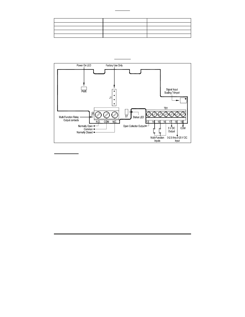
FIGURE 46
IODF LAYOUT
ANALOG INPUT
Connect the signal input to Terminal "18" and the common to Terminal "19". Connect the Start
(Jumper) to Terminal "9" (ON THE DRIVE), which is factory set for N.O. Start ("0010") and to
either common Terminal "4" or "11".
SCALE Trimpot: If the input Signal is higher than 25 Volts DC, use the SCALE Trimpot to
attenuate it. Apply the maximum signal input and set the drive for full speed output and observe
the display. Rotate the SCALE Trimpot counter clockwise until the drive output frequency begins
to drop. Then, rotate the SCALE Trimpot clockwise until the display returns to the maximum
output frequency.
Set the signal Slope and Type and adjust the Gain, Offset, and Response Time as desired.