KB Electronics KBDF-48 User Manual
Page 26
26
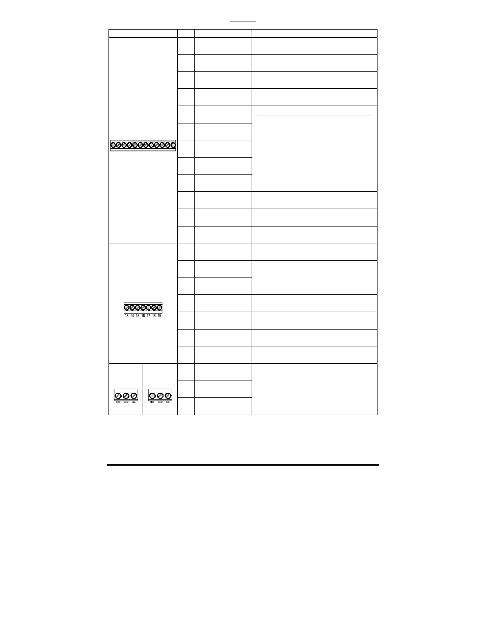
TABLE 7
DRIVE INPUT AND OUTPUT CONNECTIONS
1
Terminal Blocks
No.
Description
Specifications
1
Power Supply
–5 Volts DC at 1 mA Max.
2
Power Supply
+5 Volts DC at 1 mA Max.
3 Analog Signal Input
0 – ±5 / ±10 Volts DC,
0 – 20 / 4 – 20 mA DC
4
Common
2
──
5 MFIT
1
6 MFIT
2
7 MFIT
3
8 MFIT
4
9 MFIT
5
N.O. Contacts or NPN / PNP Transistors
7 Preset Frequencies,
Up Frequency Command,
Down Frequency Command,
Accel/Decel #2,
Forward/Stop Command,
Reverse/Stop Command,
External Fault (N.O. Contact), Reset, N.O.
Start (2-Wire or 3-Wire Start/Stop), N.C.
Stop (3-Wire Start/Stop),
External Fault (N.C. Contact)
10
External
Power Supply Input
5 – 24 Volts DC Input
11
Common
2
──
TB1
on Drive
3
1 2
4 5 6
8
7
9
11
10
12
12
Analog Output
0 – 5 Volts DC
13
Open Collector
Output
NPN
14 MFIT
6
15 MFIT
7
Same As
MFIT 1 – MFIT 5 Above
16
Common
2
──
17
Power Supply
+5 Volts DC at 1 mA Max.
18
Analog Input #2
0 – 2.5 thru 0 – 25 Volts DC
TB1
on IODF
19
Common
2
──
N.O. Normally
Open
COM Relay
Common
3
TB2
on Drive
TB3
on IODF
N.C. Normally
Closed
Run, Fault,
Target Frequency (5.03 ± 5.04),
Frequency Threshold Level (> 5.03 –5.04),
Frequency Threshold Level (< 5.03 +5.04),
I
2
t or I•t Fault, Load Loss (See 5.05),
External Fault
Notes: 1. For additional inputs and outputs, install the optional IODF Input/output Multi-Function
Expansion Module (Part No. 9646). See Appendix A, on page 64. 2. Common Terminals "4",
"11", "16", and "19" are internally wired together. 3. Relay Commons are not internally wired to
Common Terminals "4", "11", "16", and "19".