Mode transition diagram 20 – IAI America IA-T-XD User Manual
Page 29
7. Mode
Transition Diagram
20
Select the
program No.
and press retur
Select the step No.
and press return
Function key
n
Step data
input
(Program)
(Modify)
* After writing data with [WRT], move to the
next step
* Move to the symbol edit mode with “Sym”
(Copy/Move)
(Clear)
Select the symbol type with the function key
Symbol/
Definition
value input
(Symbol)
* After writing data with [WRT], move to
the next edit No.
Select the parameter type with the function key
Parameter
input
(Parameter)
* After writing data with [WRT], move to
the next edit No.
Select the program No.
and press return
Function key
Function key
Move to the mode according to the
current condition
(Program
operation)
(Current
position)
(Continuous
execution)
(Step
execution)
(Execution)
Step
execution
completed
(Local flag)
Function key
(Execution
stop)
(Suspend step)
(Local
variable)
(Integer
variable)
(Program
error display)
(Real
variable)
* Only during
program stop
(String
variable)
(Task status
display)
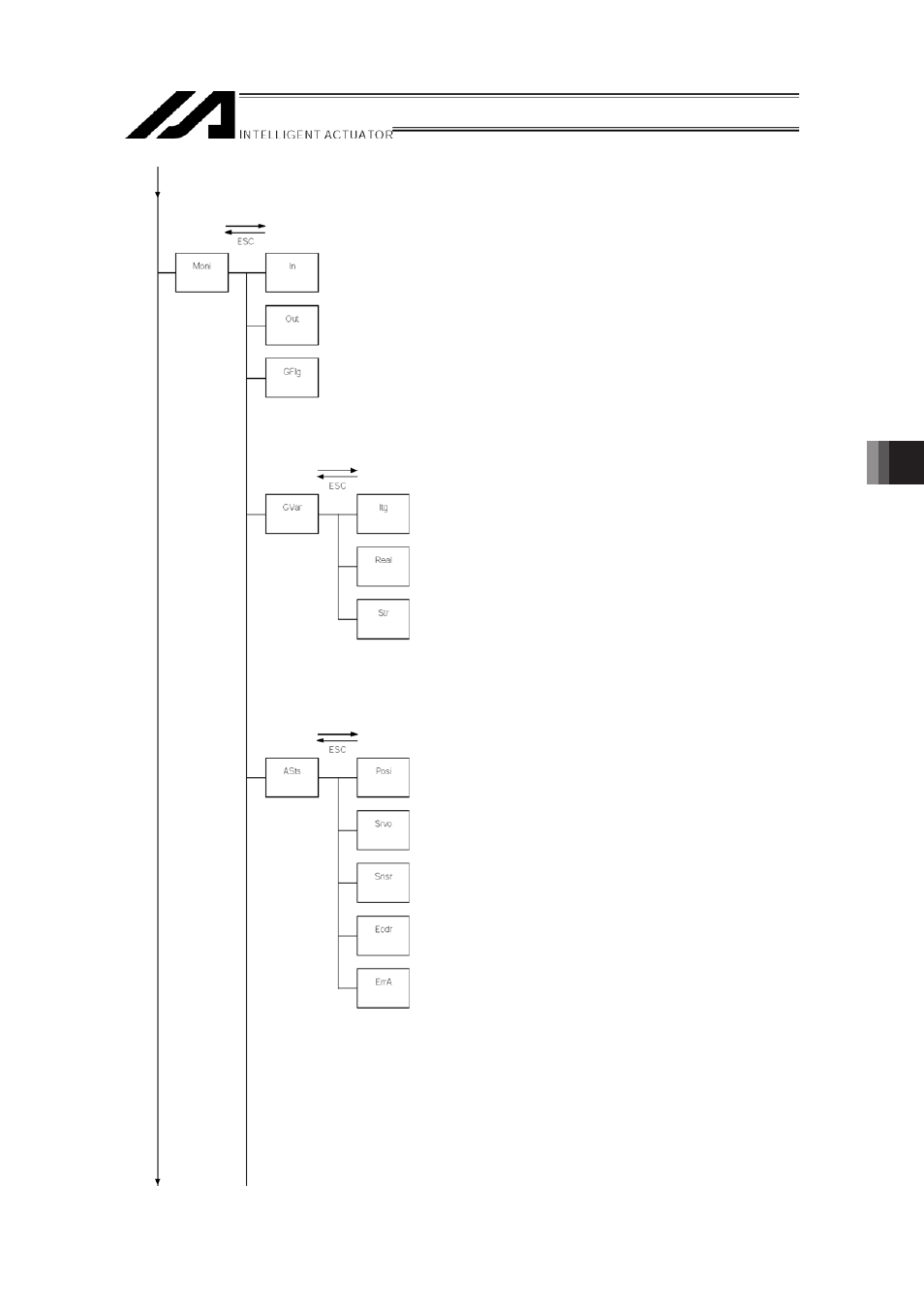
21
Function key
(Monitor)
(Input port)
(Output port)
(Global flag)
Function key
(Global
variable)
(Integer
variable)
(Real
variable)
(String
variable)
Function key
(Current
position)
(Axis status)
(Servo status)
(Sensor input
status)
(Encoder
status)
(Axis-related
error)