IAI America IA-T-XD User Manual
Page 141
*Supplement
132
Supplement
Return the slave-axis value for the “each-axis parameter No. 83 synchro slave axis coordinate
initialization cancel” to the original value.
Mode Transition:
Press the WRT key to transfer the data.
Advance to the next parameter screen. Move to the
Flash ROM writing screen with the ESC key.
Write the data to Flash ROM.
Press the F1 (Yes) key.
Restart the controller.
Press the F1 (Yes) key.
Slave axis
133
Supplement
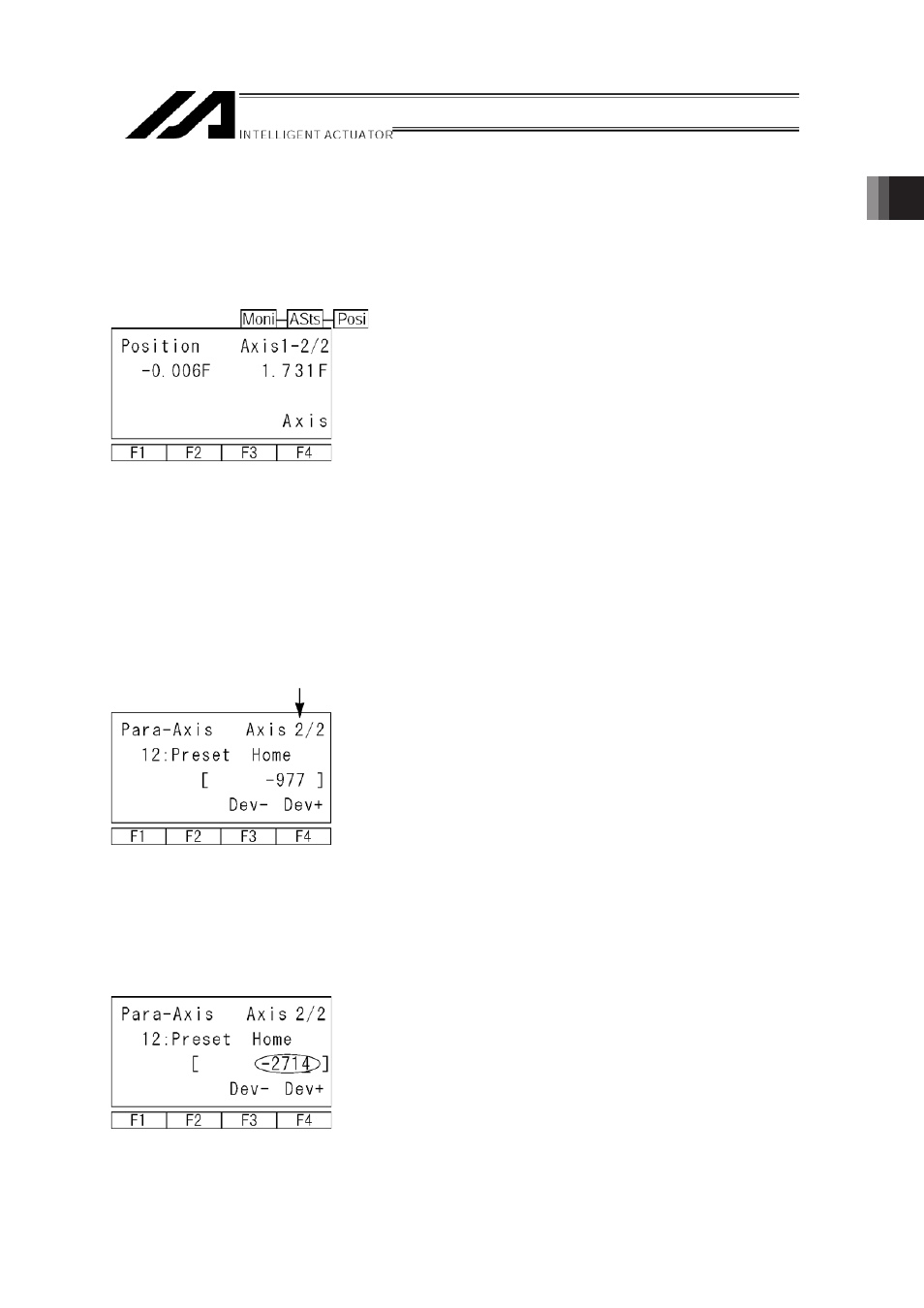
(5) Set the preset home value to uniform the coordinate values of the master and slave axes.
㽲
If the controller 7 segment display is “rdy” while the servo is OFF, read the displayed
current positions of the master and slave axes.
(If the error No. C74 real position soft limit over error occurs, reset the error. When “rdy” is
displayed, the current positions can be read.)
Mode Transition:
* If the servo is turned ON at this stage, error No. D0A driver overload error, error No. C6B
deviation overflow error, error No. CA5 stop deviation overflow error, etc., occurs.
㽳
Calculate the following:
Each-axis parameter No. 12 preset home value for slave axis [0.001 mm]
+ ((displayed current position value for master axis [mm] - displayed current position
value for slave axis [mm]) u 1000)
Slave axis
In this example:
-977 + ((-0.006-1.731) u 1000)) = -2714
㽴
Input the calculation result in 㽳 above to the “each-axis parameter No. 12 preset home
value” for the slave axis.
After pressing the return key, press the WRT key to
transfer the data.
Move to the Flash ROM writing screen with the ESC
key.