Mode transition diagram – IAI America IA-T-XD User Manual
Page 27
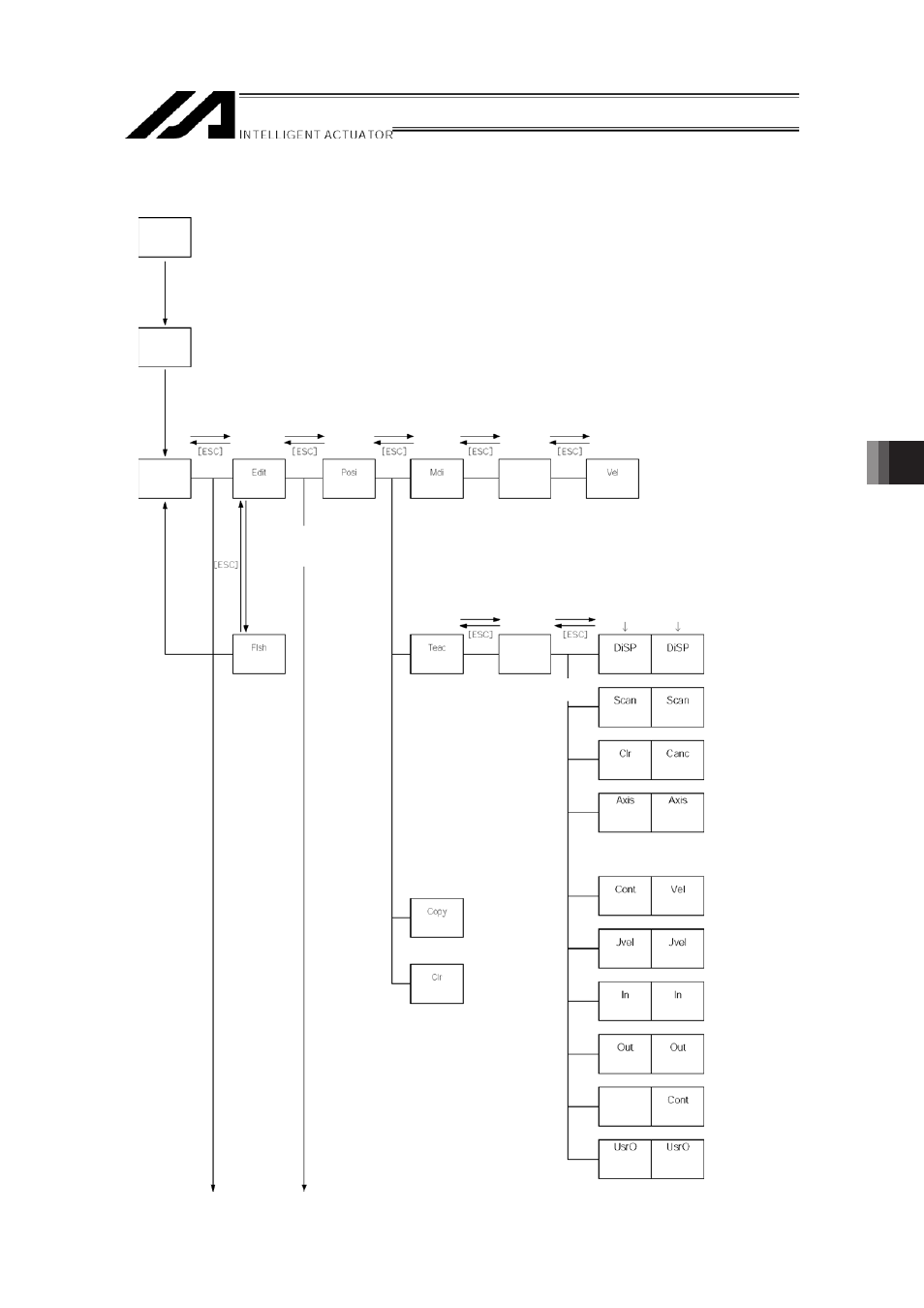
7. Mode
Transition Diagram
18
##
>F 8 >F
Confirms the input data and moves the cursor position forward .
#$ ,1 9 H ,1 / :6 >F
Increment or decrement edit and display item No. (Position No., Program No., Step No., etc.)
#% 6" 00 >F
Switches servo ON or OFF of axes. (It is valid within Teac (teach) mode area)
#& 2 >F
Executes homing. (It is valid in the Teac (teach) mode area with the servo ON )
#' >F
Starts actuator movement or continuous movement. (It is valid in the Teac (teach) mode area
with the servo ON.)
#( >F
Stops actuator movement or continuous movement. (It is valid in the Teac (teach) mode area
with the servo ON.)
#)
#
#
$
$
%
%
&
&
4@ >FB
1 Minus direction jog movement for the 1st axis and 5th axis
1
Plus direction jog movement for the 1st axis and 5th axis
2 Minus direction jog movement for the 2nd axis and 6th axis
2
Plus direction jog movement for the 2nd axis and 6th axis
(It’s valid in the Teac (teach)
mode area with the servo
ON
3 Minus direction jog movement for the 3rd axis
3
Plus direction jog movement for the 3rd axis
4 Minus direction jog movement for the 4th axis
4
Plus direction jog movement for the 4th axis
Such jog actions with the JOG button are also valid for any not-homed axes. However,
coordinate values in this case have no meaning. Therefore, be extremely careful about
interference with the stroke end.
If jog operation is performed to the axis in action under the operation-button-acceptable
condition, the operation of the applicable axis is aborted when the JOG operation button is
turned OFF. (The next operation starts, if any.)
.@
Note : For the Linear Servo actuator, LSAS-N10/N15 quasi absolute type, the actuator
moves in a range of approximately 16mm from the stop position when a home
return operation is conducted after the power is turned on to confirm the current
position. Watch the actuator movement during operation.
19
) @B@/?
(User-specified
output port
monitor)
(User-specified
output port
monitor)
* TP application Ver. 1.05 or later only.
The above are effective only for the
5-axis/6-axis spec. controllers.
(Axis No.
display
change)
(Axis No.
display
change)
* After writing data with [WRT],
move to the next position
Position data
input
(Continuous
movement)
(Jog velocity)
(Output
monitor)
(Input
monitor)
(Continuous
movement)
(Jog velocity)
(Output
monitor)
(Velocity data)
(Input
monitor)
(Cancel)
(Data import)
(Display
change)
(Clear)
(Data import)
(Display
change)
Cursor
position data
Cursor
position No.
(Velocity
input)
Function key
(Copy/Move)
(Clear)
(Teach)
Select position No. and
press return
Function key
(Write to
Flash ROM)
“Yes” or “No”
* When escaping the mode
with [ESC], check whether to
write to Flash ROM.
* After writing data with [WRT],
move to the next position
Manual input)
Position data
input
(Position)
(
Select position No. and
press return
Function key
Function key
Function key
Mode
selection
Communications
established
Power ON