4 wiring diagram, 64 7. specifi cations – IAI America IX-NNN8040 User Manual
Page 72
64
7. Specifi
cations
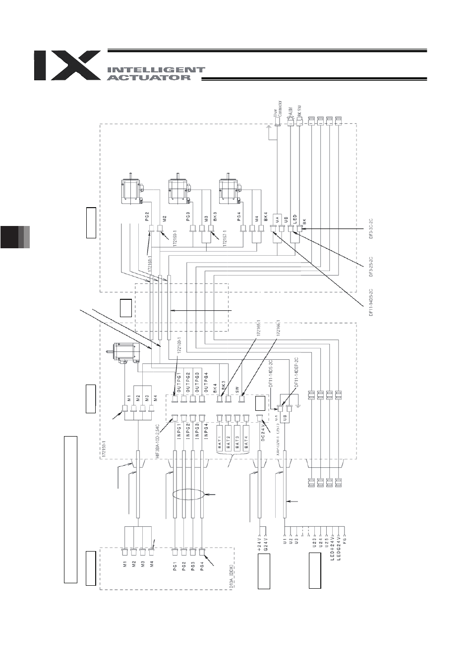
Wiring
/Pipin
g Dia
gr
a
m (Arm Le
n
g
th
: 50
0/6
00)
Co
ntroller
C
a
bl
e f
ix
c
a
p
(C
ap
con
)
M
cab
le
(ou
ts
id
e
r
o
bo
t)
P
G
cab
le
(ou
tsi
d
e
robo
t)
BK po
wer
c
a
b
le
(
outs
ide r
obot
)
U
cabl
e (
o
u
tsi
de
r
ob
o
t)
Br
ake
p
o
w
e
r
terminal
s
Us
e
r w
iri
ng
te
rminals
Insi
d
e b
a
s
e
S
e
rvo
mo
to
r f
o
r a
x
is 1
(a
rm
1
)
Bo
a
rd
F
G
(T
o
ba
se
)
Air
jo
in
t, re
d
(
I
6)
Air
jo
in
t, y
e
llo
w
(
I
6)
Air
jo
in
t, b
la
ck
(I
4)
Air
jo
in
t, w
h
ite
(
I
4)
F
le
x
ib
le
ca
bl
e
In
s
ide
ar
m 2
P
G
c
abl
e (
insi
de r
ob
o
t)
M c
a
bl
e
(i
n
s
id
e r
o
b
o
t)
U c
a
b
le
(
insi
de
r
o
b
o
t)
Se
rvo m
ot
or
f
or
ax
is
2
(a
rm
2
)
Se
rvo m
o
to
r w
it
h
br
a
k
e f
or
ax
is
3
(Z
-a
xis)
Se
rvo m
o
to
r w
it
h
br
a
k
e f
or
ax
is
4
(R
-axi
s)
FG (
to
D-
s
u
b
ho
u
s
ing)
D-
su
b
c
on
nec
tor
f
or
us
e
r
w
ir
ing
(
25-
pi
n,
s
ock
et
)
A
lar
m LED
Bra
ke
-re
lea
s
e
sw
it
c
h
f
o
r
a
x
e
s 3
/4
(Z/R
-a
xe
s
)
A
ir jo
in
t, re
d
(
I
6)
A
ir jo
in
t,
y
e
llow
(
I
6)
A
ir jo
in
t,
b
la
ck (
I
4)
A
ir jo
in
t,
w
h
ite
(
I
4)
D
e
d
ica
ted
ba
tte
rie
s f
o
r
IX:
A
B
-3
D
W
G
No.
106
865
5
*
Pl
u
g
GI
C
2
.5
/4
-S
TF
-7
.62
(P
ho
eni
x)
C
o
nne
cto
r
S
o
cke
t
(H
ir
ose)
(H
ir
o
s
e
)
Pl
ug
Plu
g
Plu
g
Pl
u
g
So
c
k
et
S
o
cke
t
S
o
cke
t
(Hiro
se
)
(H
ir
o
s
e
) (H
ir
o
s
e
)
P
lug
-i
n c
on
nec
tor
C
ontac
t J
K
-S
P2
14
0
(
J
ST)
Co
n
ta
ct co
de
D
W
G
No.
106
936
3
*
D
W
G
No.
10
6865
1*
(T
y
c
o
El
ec
tr
o
n
ic
s
AM
P)
C
o
nne
cto
r
D
W
G
No.
10
6865
6*
D
W
G No.
106
865
7
*
(H
ir
ose)
(T
y
c
o E
lec
tronic
s
AM
P
)
(T
y
co
Ele
c
tron
ic
s
A
MP
)
(T
y
c
o El
e
c
tr
oni
c
s
A
MP
)
S
o
cke
t
Sock
et
S
o
c
k
e
t
DW
G N
o
.
10
693
64
*
Notes
(1)
T
he actual l
a
y
out
of boa
rd conn
ectors varies fro
m
t
his dra
w
ing.
(2)
S
ince the br
ake
po
w
er circui
t
is
provided on the pr
im
ar
y
si
de (
high-
volt
age s
ide)
, a d
edic
a
ted 24 V
po
w
e
r suppl
y
is
r
eq
uire
d for this
circuit.
T
he 24
V
po
w
er suppl
y fo
r
I/O
ci
rc
uit
s used on the secondar
y side (lo
w
-volt
age s
ide)
c
an
not be
shared.
(3)
T
o ope
rate the
alar
m
L
E
D, the
user
m
us
t pr
ovi
de
a
c
ircuit that uses the controller I/
O
output signal.
7.4 Wiring
Diagram