2 external dimensions, Ix-nnn50, 58 7. specifi cations – IAI America IX-NNN8040 User Manual
Page 66
58
7. Specifi
cations
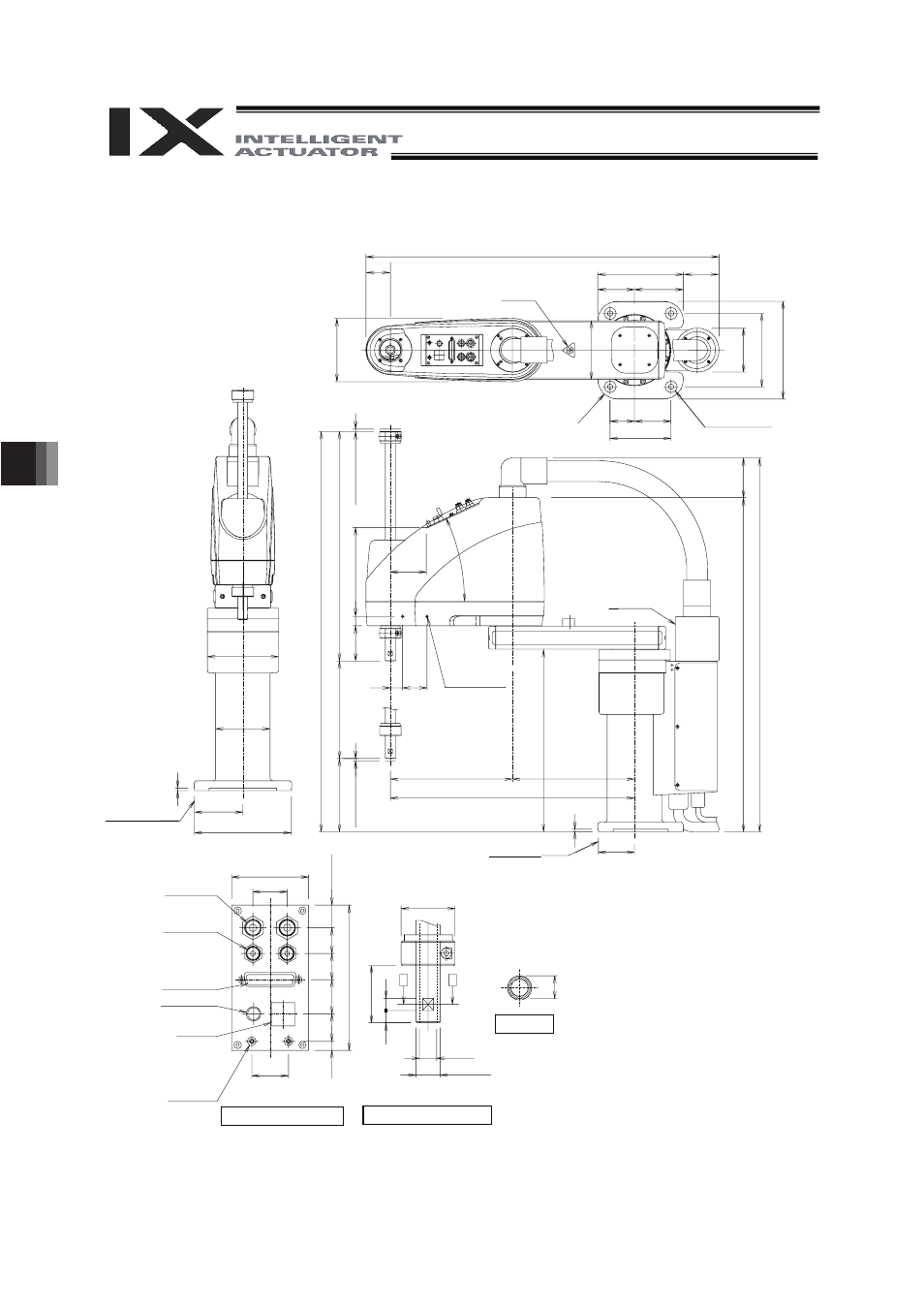
7.2 External
Dimensions
IX-NNN50
Arm 2
stopper
4 -
I 11 hole
I 24 counterbore, depth 5
5
(
M
ec
ha
ni
c
a
l
e
n
d
)
2-M4, depth 8
Same on opposite
side (*1)
5 (Mech
a
n
ic
al e
n
d
)
Arm 1
Arm 2
stopper
I 6 quick
air-tube joint
I 4 quick
air-tube joint
User Connector
D-sub 25-pin connector
for user wiring (socket),
fixing screw M2.6
ALM (*3)
BK SW
(Brake-release switch)
Spacer
Outer diameter
I 7
Height 10 (M4)
Depth 5 (*2)
Detailed view of panel (1/2)
Detailed view of arm tip (1/2)
I 14, hollow
Section A-A
*1: The holes for the 2-M4 screws (depth 8) pierce through the thickness
of the arm’s side wall. If the mounting screws are long, they will
contact the internal parts. Exercise due caution in this regard.
*2: External force applied to the spacers must not exceed 30 N in the
axial direction or 2 N
m in the rotating direction (for each spacer).
*3: The LED operates only when the user provides a circuit that receives
controller I/O output signal and supplies 24 VDC to the LED terminal
in the user connector.
Reference surface
Reference surface
Red
Yellow
Black
White
(723.2)
(50)
175 (73.2)
75 100
(1
30
)
12
0
90
15
0
20
0
50 75
125
R40
I 146
I 112
5
99
198
82
0 (9
2
0
)
47
0 [
57
0]
200
ST
[300ST
]
150
[5
0
]
72
19
(18
2.4
)
(73.2)
25 50
25
q
250 250
500
5
74
(81
.5)
(6
84
.1)
(76
5.6
)
19
I 44
A A
47
10 1
0
I 20h7 (
)
0
- 0.021
63
28
30
(1
8.
5)
7.
5
22
.5
28
21.
5
21
11
9