Ix-nnn70, 60 7. specifi cations – IAI America IX-NNN8040 User Manual
Page 68
60
7. Specifi
cations
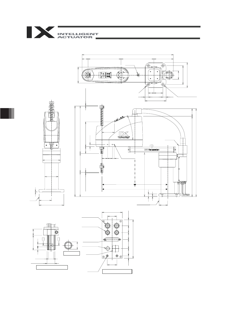
IX-NNN70
Arm 2
stopper
4 - 14 drilled
I 30 counterbore, depth 5
6
(
M
ec
ha
ni
c
a
l e
n
d
)
Arm 1
Arm 2
stopper
3-M4, depth 8
Same on opposite side (*1)
Reference
surface
6 (Mech
a
n
ic
al
e
n
d)
I 6 quick
air-tube joint
I 4 quick
air-tube joint
Detailed view of panel (1/2)
Detailed view of arm tip (1/2)
I 18, hollow
Section A-A
*1: The holes for the 3-M4 screws (depth 8) pierce through the
thickness of the arm’s side wall.
*2: External force applied to the spacers must not exceed 30 N in
the axial direction or 2 N
m in the rotating direction (for each
spacer).
*3: The LED operates only when the user provides a circuit that
receives controller I/O output signal and supplies 24 VDC to the
LED terminal in the user connector.
7
Reference surface
(971.5)
(65)
350
350
(206.5)
(1
69
)
(9
0)
20
0
26
8
(R55)
60 95
(34) 155 (34)
223
(
I 188)
(
I 144)
131
262
96
2 [
1
1
6
2
]
50
4 [704st]
25
8 [
5
8
]
2
0
0
s
t
[4
0
0
st]
73
(26
3.
4)
22
.5
(134.6)
25
q
61 51 20
46
8
(85
3) (8
1)
(93
4)
91
28
7
20
47
10
10
I 25h7(
)
A
A
0
- 0.021
23
.5
63
28
30
(18
.5
)
7
.5 22
.5
28
21
.5
21
1
19
Red
Yellow
Black White
User Connector
(D-sub 25-pin connector
for user wiring (socket),
fixing screw M2.6)
ALM (*3)
BK SW
(Brake-release switch)
Spacer
Outer diameter
I 7
Height 10 (M4)
Depth 5 (*2)
350 350
700