3 how to installation, 1 installation of the main unit, 2 attachment surface – IAI America RCP2-SRGD4R User Manual
Page 37: 3 tightening screws
2. Installation
31
2.3 How to Installation
This chapter explains how to install the actuator on your mechanical system.
2.3.1 Installation of the Main Unit
Tapped holes are provided on the front face, rear face, right/left side faces and bottom face of the
actuator
so that the actuator can be installed from any of these five directions.
The tapped hole size varies depending on the mounting surface. (Refer to 6, “External Dimensions.”)
Front face/rear face: M6, depth 12
Right/left side faces/bottom face: M4, depth 10
Caution: Select the bolt length carefully. If bolts of an inappropriate length are used, the tapped
holes may be damaged or sufficient actuator installation strength may not be
achieved, resulting in lower precision or unexpected accidents.
2.3.2 Attachment Surface
• The mounting table should have sufficient rigidity to avoid generating vibration.
• The surface where the actuator will be mounted should be machined or be equally level and the
flatness tolerance between the actuator and the table should be within 0.05mm.
• Provide enough space around the actuator to permit maintenance work to be done.
2.3.3 Tightening Screws
• Use hexagonal socket head bolts for mounting male threads.
• Use of high-strength bolts of ISO-10.9 or higher is recommended.
• Make sure to have the effective length of screw engagement described below or more for the
tightening of a bolt and a female screw.
When female screw is on steel ĺ thread length same as nominal diameter
When female screw is on aluminum ĺ 1.8 times of nominal diameter
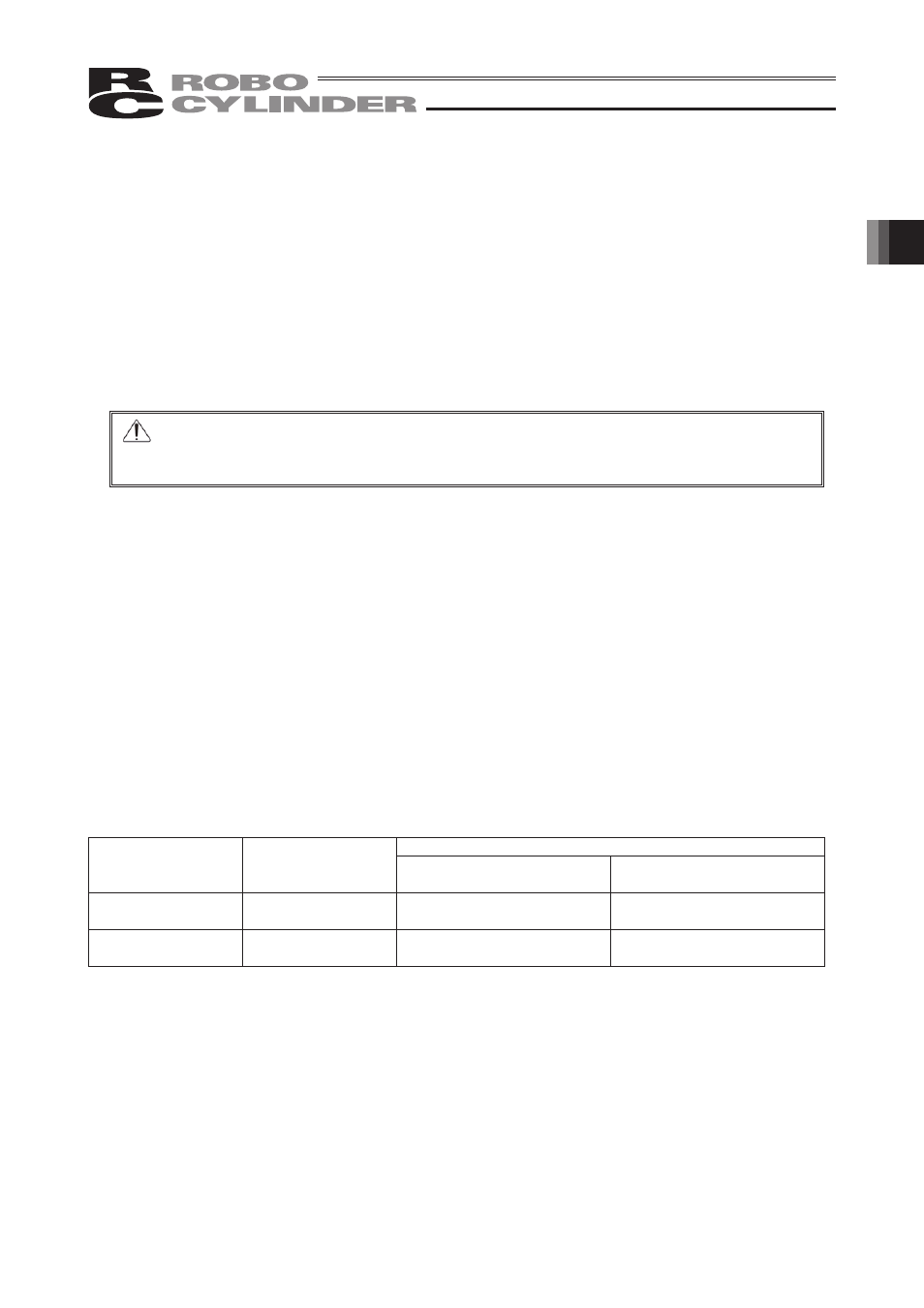
Recommended tightening torques are as follows.
Tightening Torque
Mounting Location
Nominal Thread
Size
Bolt bearing surface is made
of steel
Bolt bearing surface is made
of aluminum
Front face/rear face
M4
3.59 N•m (0.37 kgf•m)
1.76N•m (0.18 kgf•m)
Right/left side
faces/bottom face
M6
12.34 N•m (1.26 kgf•m)
5.36N•m (0.55 kgf•m)