Gilderfluke&Co BR-SDC Serial Device Controller User Manual
Page 42
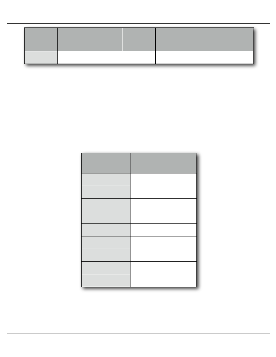
Binary
Number
Bit3
Pin #6
(+8)
Bit2
Pin #7
(+4)
Bit1
Pin #8
(+2)
Bit0
Pin #9
(+1)
Multiplexer
Selected
8
On
Off
Off
Off
Tx = #8, Rx = #8
This mode is often used with a PLC or other controller, where GPIOs are
available for making the binary selections.
Note that when using the binary inputs, it is not possible to transmit through
more than one multiplexer output at one time, unless you want to transmit to all
of them simultaneously.
You donʼt want to switch between multiplexers in the middle of a message.
Make sure that the last serial message has completed transmission before you
change the selected multiplexer.
3) (Available in mode #1 ONLY) Commands can be embedded into the strings
that select the following:
String
Entry
Multiplexer
Selected
Mux0
Mux1
Mux2
Mux3
Mux4
Mux5
Mux6
Mux7
Mux8
Tx = ALL, Rx = #1
Tx = #1, Rx = #1
Tx = #2, Rx = #2
Tx = #3, Rx = #3
Tx = #4, Rx = #4
Tx = #5, Rx = #5
Tx = #6, Rx = #6
Tx = #7, Rx = #7
Tx = #8, Rx = #8
Note that when using the binary inputs, it is not possible to transmit through
more than one multiplexer output at one time, unless you want to transmit to all
of them simultaneously.
2) Mode 1: This mode of operation is combination of mode 0 and mode 2. Strings
Gilderfluke & Co.• 205 South Flower Street • Burbank, California 91502 • 818/840-9484 • 800/776-5972 • fax 818/840-9485
Br-SDC Manual / December 30, 2013 9:24 AM / page 42 of 62