Gilderfluke&Co BR-SDC Serial Device Controller User Manual
Page 28
String
Sent
Multiplexer
Selected
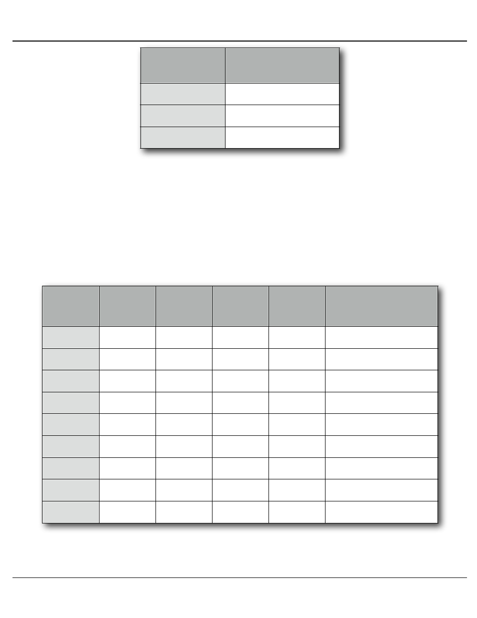
AT+++6
AT+++7
AT+++8
Tx = #6, Rx = #6
Tx = #7, Rx = #7
Tx = #8, Rx = #8
If more numbers (1-8) are received before the
choose to route data to more than one of the multiplexed ports a the same time.
The first valid number between 1 and 8 sets the port that will be used of receiving
serial data and routing to the Br-SDC8ʼs ʻConfig./Mux. RS-232 portʼ (female DE-
09) or ʻMux./RS-422ʼ (female Rj-12) ports.
As an example, to send serial data out ports 3, 5, and 7, and listen to port 5 for
any serial data which is returned, you would send the string: ʻAT+++537
2) ¼-J6 input bits 0, 1, 2 and 3: A binary pattern of bits presented on these four
input pins will select which multiplexer output is to be used:
Binary
Number
Bit3
Pin #6
(+8)
Bit2
Pin #7
(+4)
Bit1
Pin #8
(+2)
Bit0
Pin #9
(+1)
Multiplexer
Selected
0
1
2
3
4
5
6
7
8
Off
Off
Off
Off
Tx = ALL, Rx = #1
Off
Off
Off
On
Tx = #1, Rx = #1
Off
Off
On
Off
Tx = #2, Rx = #2
Off
Off
On
On
Tx = #3, Rx = #3
Off
On
Off
Off
Tx = #4, Rx = #4
Off
On
Off
On
Tx = #5, Rx = #5
Off
On
On
Off
Tx = #6, Rx = #6
Off
On
On
On
Tx = #7, Rx = #7
On
Off
Off
Off
Tx = #8, Rx = #8
This mode is often used with a PLC or other controller, where GPIOs are avail-
able for making the binary selections.
Gilderfluke & Co.• 205 South Flower Street • Burbank, California 91502 • 818/840-9484 • 800/776-5972 • fax 818/840-9485
Br-SDC Manual / December 30, 2013 9:24 AM / page 28 of 62