Gilderfluke&Co BR-SDC Serial Device Controller User Manual
Page 11
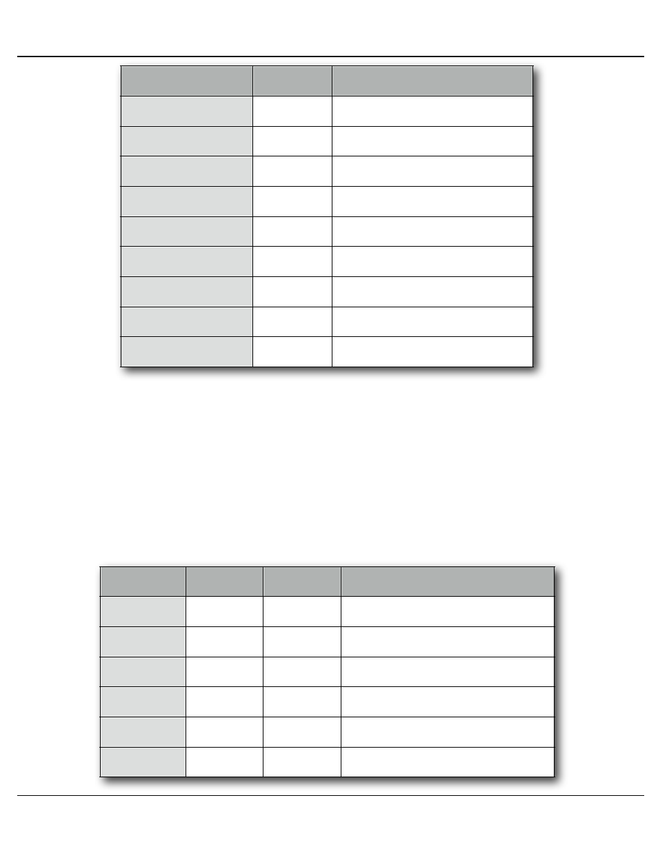
POSITION
WIRE #
SIGNAL NAME:
TOP-LEFT
TOP-RIGHT
BOTTOM-LEFT
BOTTOM-RIGHT
1
n/c
2
RS-232 Tx from Br-SDC
3
RS-232 Rx to Br-SDC
4
n/c
5
Ground
6
n/c
7
n/c
8
n/c
9
n/c
b) RS-422 (female Rj-12):
The single port Br-SDC/422 replaces the RS-232 port with a RS244 serial port.
On the eight port Br-SDC8, the RS-232 serial port is paralleled with the RS-244
serial port. You can use either port interchangeably, but not at the same time.
The serial data signals from the Br-SDC are brought out on a six position RJ-
12 (six position, six conductor modular telephone style connector) on the card
cage. Facing the end of the cable with the release latch upwards, its pin out is as
follows:
POSITION
WIRE #
COLOR
SIGNAL NAME:
LEFT
RIGHT
1
white
Signal Ground
2
black
- Serial data out from Br-SDC
3
red
+ Serial data out from Br-SDC
4
green
- Serial data in to card
5
yellow
+ Serial data in to card
6
blue
Signal Ground
Gilderfluke & Co.• 205 South Flower Street • Burbank, California 91502 • 818/840-9484 • 800/776-5972 • fax 818/840-9485
Br-SDC Manual / December 30, 2013 9:24 AM / page 11 of 62