Ronan XSD-1000 User Manual
Page 66
65
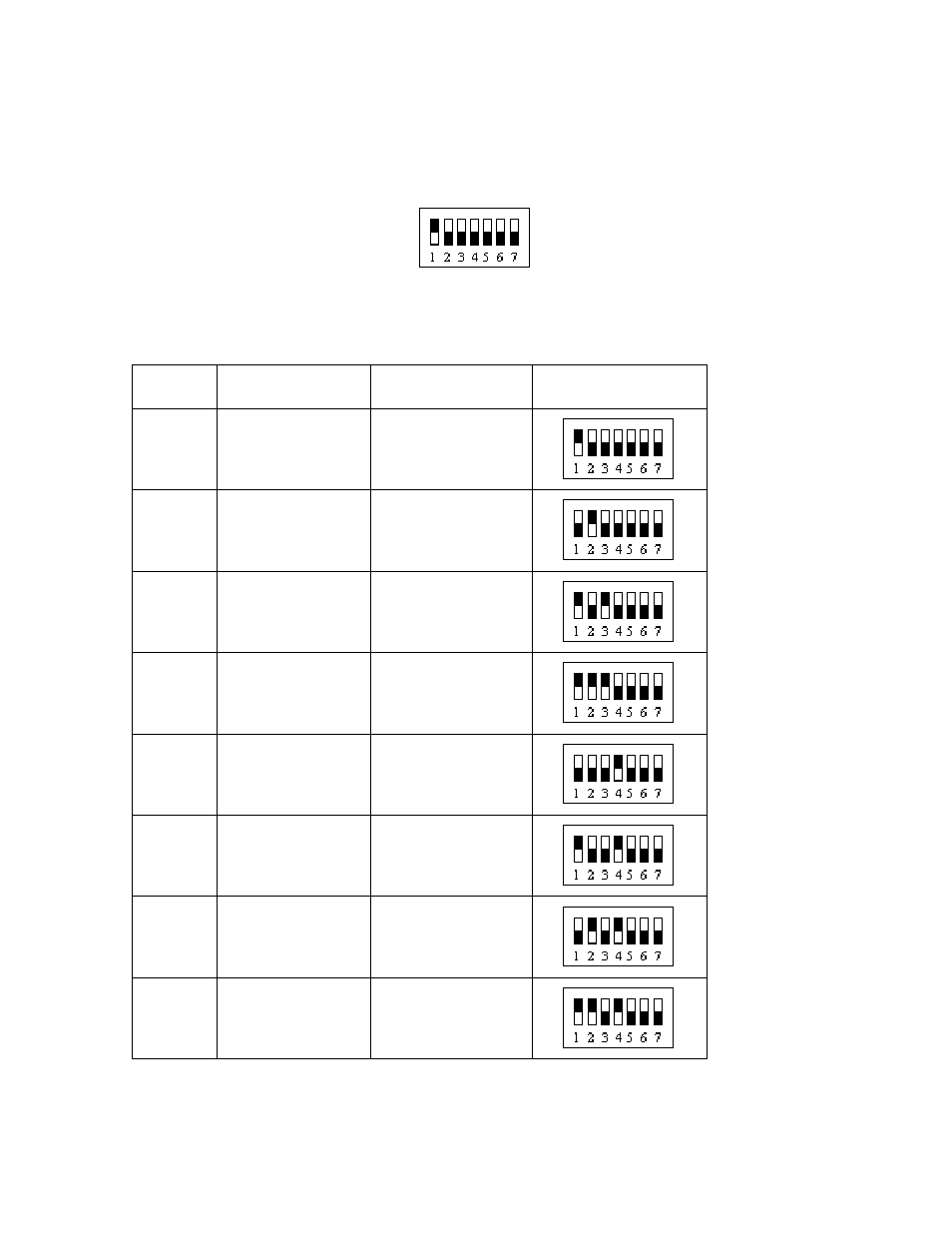
Remote I/O Module Addressing
In the following illustrations, the slider on each switch position 1 – 7, should match the
black portion of each switch. For instance:
in this illustration, switch position 1 is On (up), positions 2 through 7 are Off (down).
This chart illustrates the proper addressing for each Remote I/O Module:
Module
Address
Module Type
Description
Switch Positions
1
3-30VDC Input
Photo-eyes 1 - 4
2
3-30VDC Input
Photo-eyes 5 - 8
5
Relay Output
Auto Verification
Annunciator
7
Scintillator Input
Detector 1A
8
Scintillator Input
Detector 2A
9
Scintillator Input
Detector 3A
10
Scintillator Input
Detector 4A
11
Scintillator Input
Detector 5A